Radar apparatus

a technology of radar and target, applied in the field of radar equipment, can solve the problem of low reliability and achieve the effect of low reliability

Active Publication Date: 2015-08-06
FUJITSU GENERAL LTD
View PDF8 Cites 6 Cited by
  • Summary
  • Abstract
  • Description
  • Claims
  • Application Information

AI Technical Summary

Benefits of technology

The patent aims to prevent the vehicle controller from making errors in controlling the vehicle based on information from the target shown on the peak angle. The patent aims to improve the reliability of the data used for controlling the vehicle.

Problems solved by technology

The technical problem addressed in this patent text is the limitation of angle estimation systems in accurately identifying the angle of multiple targets that are at the same distance and reflecting waves from the targets. This can lead to lower reliability of the angle estimates and potentially incorrect control based on incorrect information about the target.

Method used


Image

  • Radar apparatus
  • Radar apparatus
  • Radar apparatus

Examples


Embodiment Construction

[0031]Hereinafter, some embodiments of the invention are described based on attached drawings.

[0032]

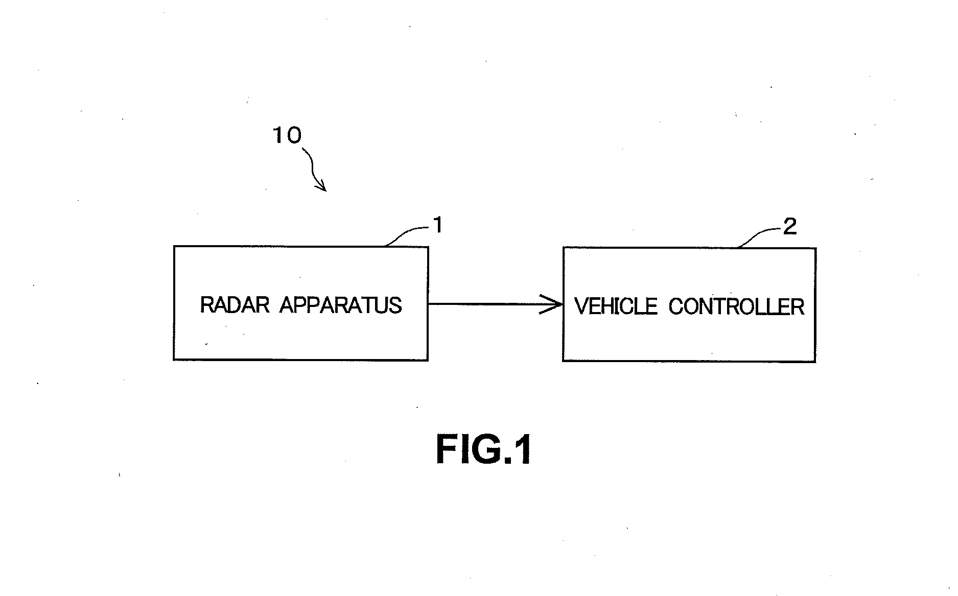
[0033]FIG. 1 shows a schematic configuration of a vehicle control system 10 of the embodiment. The vehicle control system 10 is installed in a vehicle, for example, in a car. Hereinafter, the vehicle in which the vehicle control system 10 is installed is referred to as “self-vehicle.” As shown in FIG. 1, the vehicle control system 10 has a radar apparatus 1 and a vehicle controller 2.

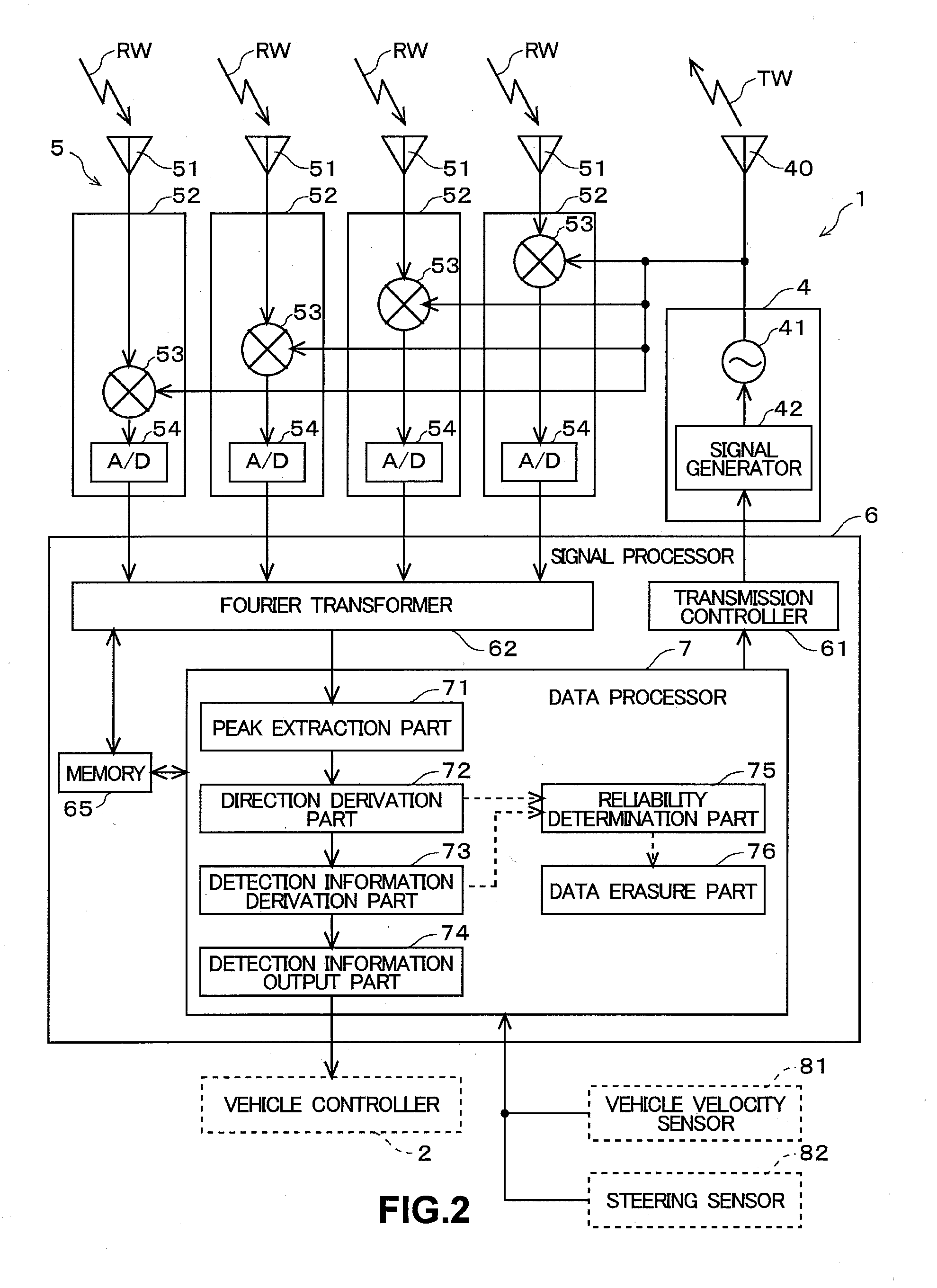
[0034]The radar apparatus 1 obtains information about a target existing in the periphery of the self-vehicle (hereinafter, referred to as “target detection information”). The radar apparatus 1 of the embodiment obtains information about a target, such as other vehicle existing in the forward of the self-vehicle, by using FMCW (Frequency Modulated Continuous Wave). The radar apparatus 1 obtains target detection information including a distance (m) to the target in the traveling direction of the self-vehicl...


PUM


Abstract

On a radar apparatus, a direction derivation part derives a peak angle related to an angle of a target based on reception signals received by a plurality of reception antennas. Then, a detection information derivation part derives, based on the peak angle, target data that are internal data about the target, and stores the derived target data into a memory. A reliability determination part determines a reliability of an object peak angle upon which the target data about the target was derived, the reliability of the object peak angle being determined based on a different peak angle derived concurrently with the object peak angle by the direction derivation part. Then, a data erasure part deletes, based on the reliability of the object peak angle determined by the reliability determination part, the target data relevant to the object peak angle from the memory to exclude the target data from further processing.

Description


Claims


Application Information

Patent Timeline
Owner FUJITSU GENERAL LTD
Why Eureka
Try Eureka