
Device for adaptive projection

a projection device and adaptive technology, applied in the field of computer projection devices, can solve the problems of reducing the performance of the projector, affecting the projection effect,

Active Publication Date: 2015-08-06
INTEL CORP
View PDF13 Cites 29 Cited by
  • Summary
  • Abstract
  • Description
  • Claims
  • Application Information

AI Technical Summary

Benefits of technology

The present invention relates to computing devices and more specifically to computer projection devices. The technical effects of the invention include the ability to calibrate and adjust the projection device for different surface properties and angles, as well as the ability to dynamically adjust the calibration as the user moves the device. This allows for more flexibility and compatibility with different surfaces and users. Additionally, the invention includes a camera for depth sensing and 3D imaging, as well as audio speakers for improved user experience. Overall, the invention provides dynamic calibration and flexibility for computer projection devices.

Problems solved by technology

Current projection devices are typically designed for a specific projection surface and projection angle, and are not configurable for a wide range of settings.
For example, most projectors are designed to project onto a surface having a neutral tone (e.g., white) with minimal texture or reflectiveness; deviation from these surface properties reduces projector performance.
Furthermore, if a projector's position deviates from its intended projection angle (e.g., perpendicular to the target projection surface), the projected image may be distorted until a user physically adjusts the physical position of the projector by moving it around, tilting and rotating it until a non-distorted image is displayed.

Method used


Image

  • Device for adaptive projection
  • Device for adaptive projection
  • Device for adaptive projection

Examples


Embodiment Construction

[0011]Embodiments of the invention describe projection devices capable of dynamic calibration. Throughout this specification, several terms of art are used. These terms are to take on their ordinary meaning in the art from which they come, unless specifically defined herein or the context of their use would clearly suggest otherwise. In the following description numerous specific details are set forth to provide a thorough understanding of the embodiments. One skilled in the relevant art will recognize, however, that the techniques described herein can be practiced without one or more of the specific details, or with other methods, components, materials, etc. In other instances, well-known structures, materials, or operations are not shown or described in detail to avoid obscuring certain aspects.

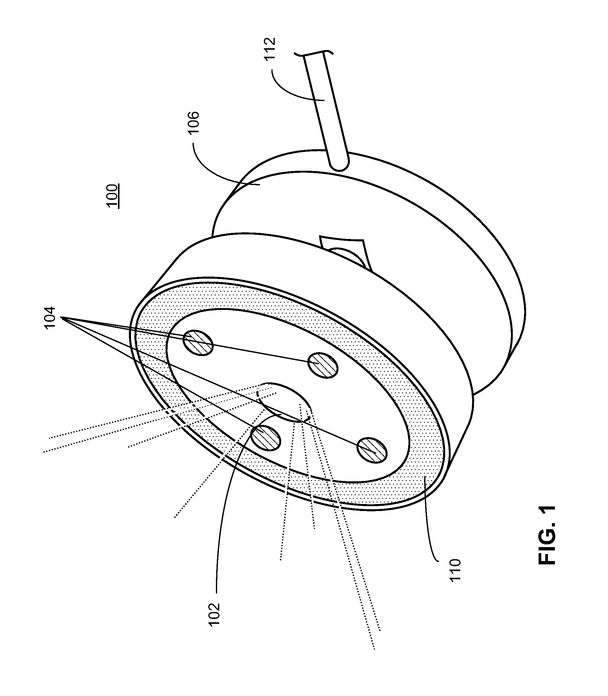
[0012]FIG. 1 is an illustration of a projector device according to an embodiment of the invention. In this embodiment, device 100 includes projector 102 which may comprise, for example, a h...


PUM


Abstract

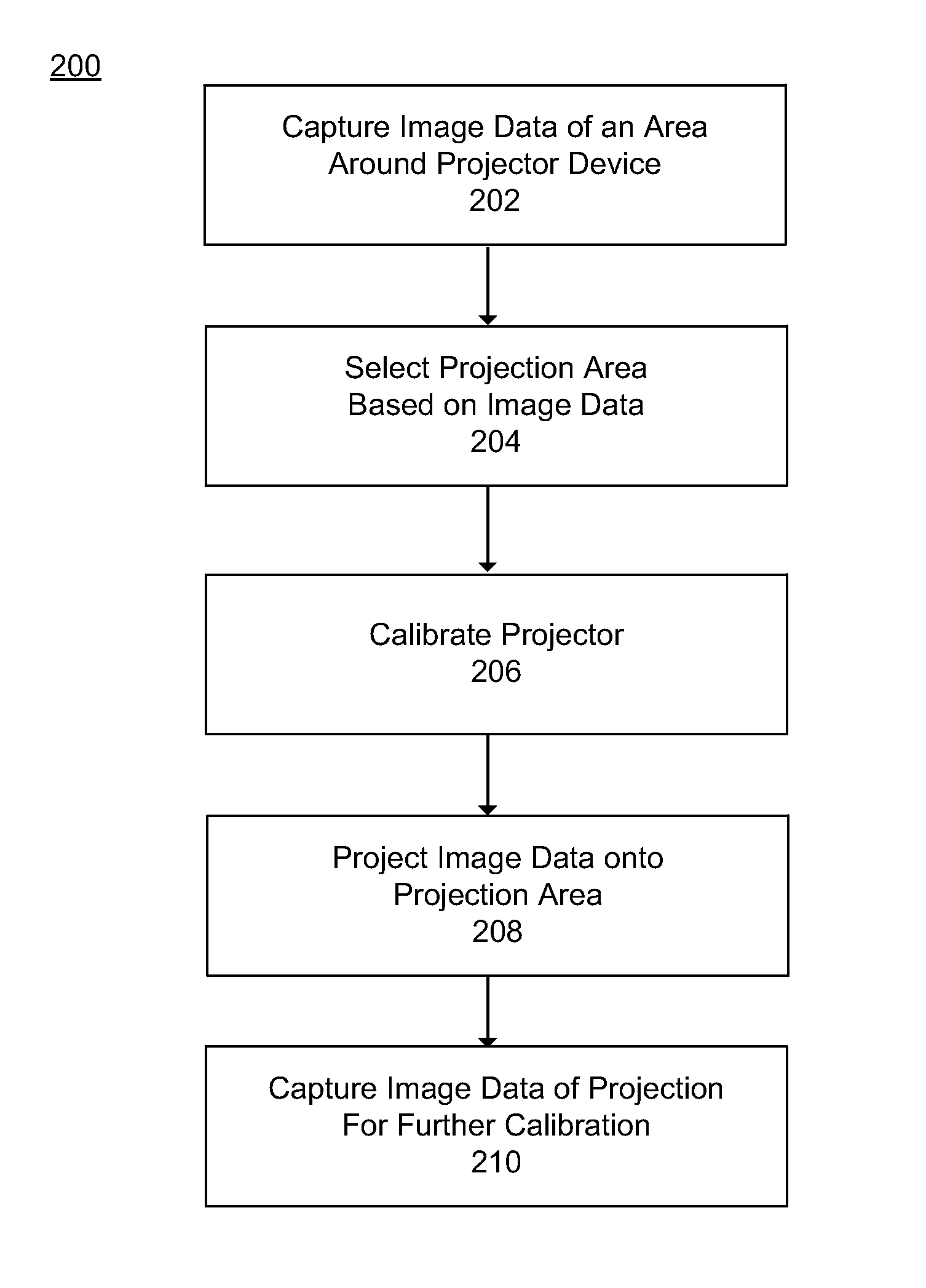
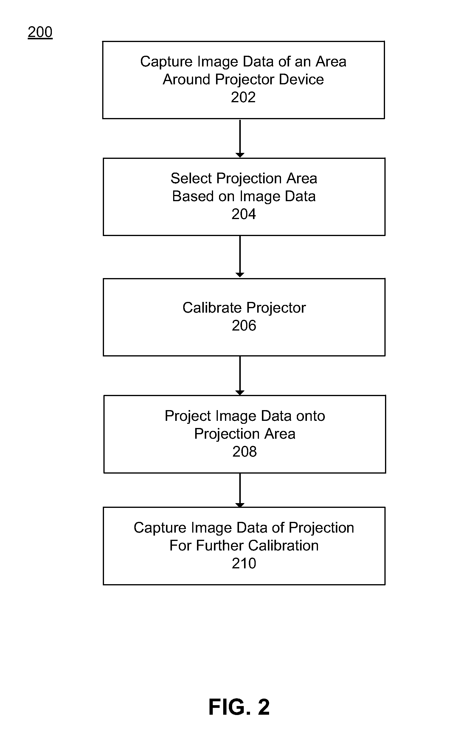
Embodiments of the invention describe apparatuses, systems and methods for dynamic projector calibration. Embodiments of the invention execute operations for capturing, via an image sensor included in a projector device, image data of an area around the projector device. Said image sensor captures 3D distance information as well as image pixel information of the surrounding area. A projection area is selected based (in part) on surface properties of the projection area determined from the image data.The projector may be calibrated (e.g., projection brightness, color balance, angle, etc.) based on the captured image data. A user I / O interface is projected onto the selected projection area, and the projector may be further (i.e., dynamically) calibrated based on captured image data of the projected user I / O interface.

Description

FIELD[0001]Embodiments of the present invention generally pertain to computing devices and more specifically to computer projection devices.BACKGROUND[0002]Current projection devices are typically designed for a specific projection surface and projection angle, and are not configurable for a wide range of settings. For example, most projectors are designed to project onto a surface having a neutral tone (e.g., white) with minimal texture or reflectiveness; deviation from these surface properties reduces projector performance. Furthermore, if a projector's position deviates from its intended projection angle (e.g., perpendicular to the target projection surface), the projected image may be distorted until a user physically adjusts the physical position of the projector by moving it around, tilting and rotating it until a non-distorted image is displayed.BRIEF DESCRIPTION OF THE DRAWINGS[0003]The following description includes discussion of figures having illustrations given by way of...

Claims


Application Information

Patent Timeline
Patent Type & Authority Applications(United States)
IPC IPC(8): H04N5/74
CPCH04N9/3182H04N9/3185H04N5/74G03B17/54G06F3/01H04N9/3194G06F3/0418G06F3/0425G06F3/0488
Inventor KWONG, WAH YIU
Owner INTEL CORP
Learn More