
Dust collecting device

a technology for collecting devices and dust, which is applied in the direction of suction handles, carpet cleaners, suction cleaners, etc., can solve the problems of reducing the size of the cover, difficult to form a large opening, and difficult to attach and detach the batteries, so as to facilitate the attachment and detachment of the batteries and the like, and without increasing the product size.

Active Publication Date: 2015-08-13
MAKITA CORP
View PDF2 Cites 30 Cited by
  • Summary
  • Abstract
  • Description
  • Claims
  • Application Information

AI Technical Summary

Benefits of technology

The present invention relates to a duct collecting device that allows for easy attachment and detachment of batteries and other components without increasing the size of the device. The invention achieves this by securing a large opening in the cover of the device without requiring a separate handle. This makes the device more convenient and user-friendly.

Problems solved by technology

On the other hand, when the product size is reduced, the cover is also reduced and it becomes difficult to form a large opening, as a result, it is hard to attach and detach the battery.

Method used


Image

  • Dust collecting device
  • Dust collecting device
  • Dust collecting device

Examples


Embodiment Construction

[0031]Hereinafter, an embodiment of the present invention will be explained with reference to the drawings.

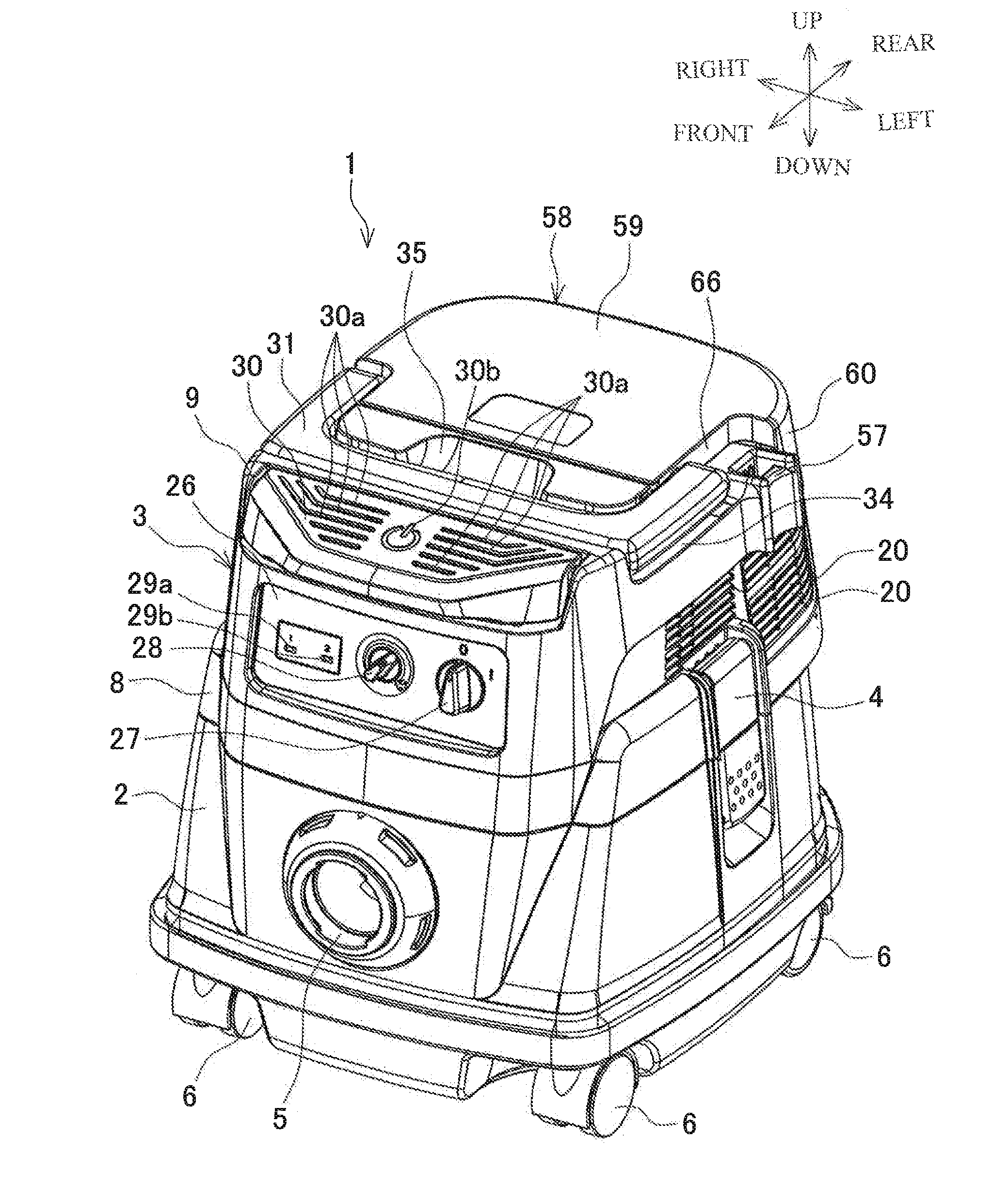
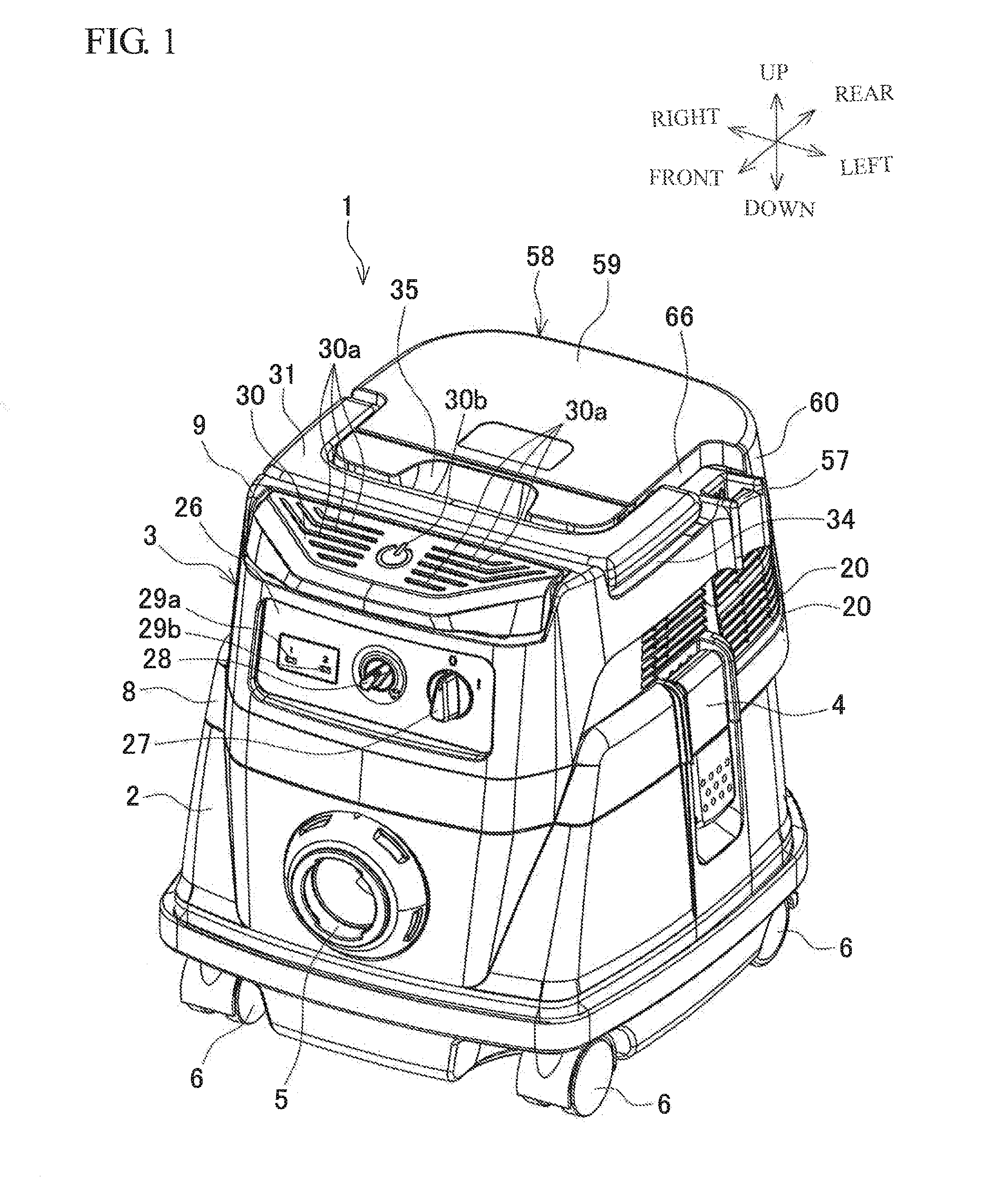
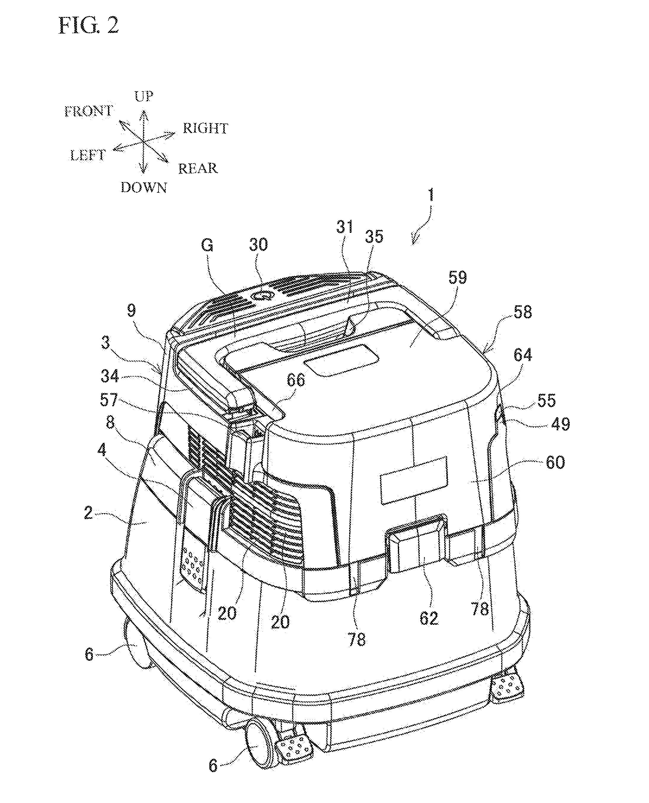
[0032]FIG. 1 and FIG. 2 are outside drawings showing an example of a dust collecting device and FIG. 3 is a vertical cross-sectional view thereof. A dust collecting device 1 includes a tank 2 whose upper end is opened, and a main body 3 that has a motor 11 as a drive part and a blower fan 16. The main body 3 is placed above a tank 2. In the state where the main body 3 is placed above the tank 2, latches 4, 4 provided right and left of the tank 2 are locked to side faces of the main body 3 so that the main body 3 is detachably connected to the tank 2. A suction opening 5 to which a not-shown hose can be connected is provided in a front face of the tank 2, and pairs of casters 6, 6 . . . (casters 6, 6 in the rear side have stoppers) are provided in front and back in a lower side of the tank 2. A guide cylinder 7 for guiding the air sucked into the tank 2 to a lower direction is p...


PUM


Abstract

A dust collecting device includes a tank and a main body housing a motor and detachably attachable to an upper part of the tank. A handle and a cover are both provided in an upper part of the main body. The handle is capable of being raised and turned down around a handle rotation shaft. The cover is capable of being opened and closed around a cover rotation shaft and covers a housing portion provided in the main body in a closed position. The cover rotation shaft is provided in parallel to the handle rotation shaft. The cover rotation shaft is positioned closer to a grip portion of the handle than the handle rotation shaft so as to overlap with a part of the handle. The handle rotation shaft is positioned closer to the cover than the cover rotation shaft so as to overlap with a part of cover.

Description

[0001]This application claims the benefit of Japanese Patent Application Numbers 2014-025616, 2014-025617 and 2014-025618, all filed on Feb. 13, 2014, the entirety of which is incorporated by reference.BACKGROUND OF THE INVENTION[0002]1. Field of the Invention[0003]The present invention relates to a dust collecting device provided with a main body having a drive part so as to be detachably attached above a tank storing the dust and the like.[0004]2. Description of Related Art[0005]A dust collecting device includes a main body that houses, for example, a motor having a blower fan as a drive part and is detachably placed above a tank. When the blower fan is rotated by driving of the motor, outside air is sucked through a hose connected to a suction opening provided in the tank and passes through the inside of the tank and the main body. During this process, the dust and the like in the sucked outside air is caught by a filter provided in the tank and stored inside the tank. A handle i...

Claims


Application Information

Patent Timeline
Patent Type & Authority Applications(United States)
IPC IPC(8): A47L5/36A47L9/32
CPCA47L9/327A47L5/365A47L9/22A47L9/2868A47L9/2884A47L9/32A47L11/4005A47L11/4075
Inventor KOURA, KENTAROYAMAGUCHI, HIROSHI
Owner MAKITA CORP
Learn More