Eureka AIR delivers breakthrough ideas for toughest innovation challenges, trusted by R&D personnel around the world.

Bladed apparatus having improved gripping

a technology of blades and blades, applied in the field of cutting tools, can solve the problems of karambits that are unstable, twisting in the operator's hand, and the design of day karambits, so as to improve the effectiveness, comfort, and usability of karambits, and increase the stability of karambits

Inactive Publication Date: 2015-08-13
IRVIN ROBERT
View PDF6 Cites 8 Cited by
  • Summary
  • Abstract
  • Description
  • Claims
  • Application Information

AI Technical Summary

Benefits of technology

The present disclosure is about a bladed apparatus with a C-shaped tool that has a safety ring portion and a blade portion with an inside edge, outside edge, and point, as well as a handle portion. The safety ring portion has a mid-lock, thumb lock, and reverse lock, and the blade portion has an inside edge, outside edge, and point. The C-shaped tool can be made from a single, continuous material, such as ferrous metal or polymer-based composite resinous material. The handle portion can be made from wood or polymer material. This invention aims to provide a tool with improved safety features and ease of use.

Problems solved by technology

The karambit's reach may be increased by employing the extended grip position; however, the extended grip position is inherently weak and results in unstable handling.
Applying downward force on the karambit with the thumb resting on the convex side of the safety ring (thumb would be effectively resting on a point) exposes another inherent weakness of the modern-day karambit design.
Under extreme conditions, the karambit might become unstable and twist in the operator's hand, or apply excessive pressure to the thumb at the point of contact (thumb contacting convex side of the safety ring).
Such conditions render the weapon less effective, and could become a nuisance to the operator.
Use of the existing safety ring design is not very effective; however, modifying the safety ring design to function more like a brass knuckle will render the karambit a better weapon.

Method used


Image

  • Bladed apparatus having improved gripping
  • Bladed apparatus having improved gripping
  • Bladed apparatus having improved gripping

Examples


example 1

[0056]As noted above, FIG. 2a illustrates an example of the novel straight edge karambit tool 200a having the mid-lock portion 201, the reverse lock portion 202, the thumb lock portion 203, and the knuckle portion 204. The mid-lock portion 201 may be fabricated from a continuous concave arc having a radius of, for example, 0.25 to 1.5 inches, more preferably from 0.375 to 1 inches, or, most preferably, about 0.75 inches. In certain aspects, the mid-lock portion 201 can be formed from multiple adjacent concave arcs connected to each other forming a concave geometry with such arcs cumulatively having the forgoing radii. That is, the total length of the arc, or arcs, forming the mid-lock portion 201 may be, for example, 0.25 inches to 1.0 inches. At the intersection of the spine 206 and the mid-lock portion 201, a convex geometry of one or multiple arcs, radius 0.025 to 0.5 inches or a flat surface length 0.008 to 0.50 inches may form the transition from mid-lock portion 201 to spine 2...

example 2

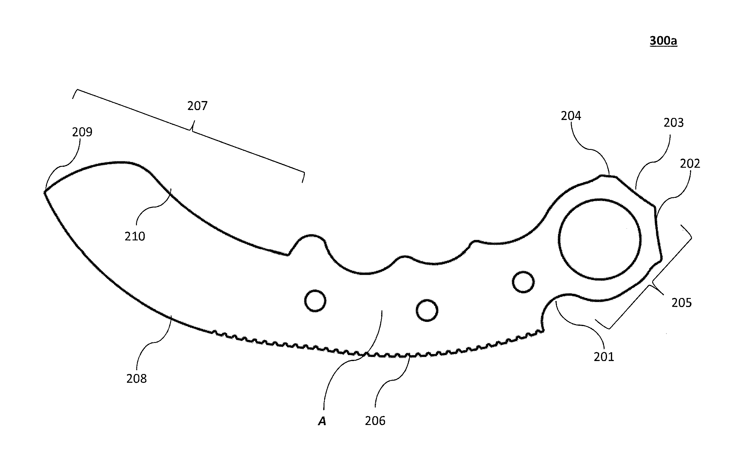
[0061]FIG. 3a illustrates an example of the novel curved edge karambit tool 300a with the added novel features, which include the mid-lock portion 201, the reverse lock portion 202, the thumb lock portion 203, and the knuckle portion 204 as described with regard to FIGS. 2a through 2h.

[0062]As will be appreciated from the figures, the straight edge karambit 200b and the curved edge karambit 300b share a number of correspondingly numbered components, which are described above and therefore will not be described in connection with the curved edge karambit tool 300a or the curved edge karambit tool 300b. FIG. 3b illustrates a curved edge karambit tool 300a in accordance with an aspect of the present invention. FIGS. 3c through 3h illustrate various views of an example curved edge karambit 300b assembled with a handle 214. Specifically, FIG. 3c illustrates a top plan view of the curved edge karambit 300b with an example handle assembly 214, while FIG. 3d illustrates the opposite side o...

example 3

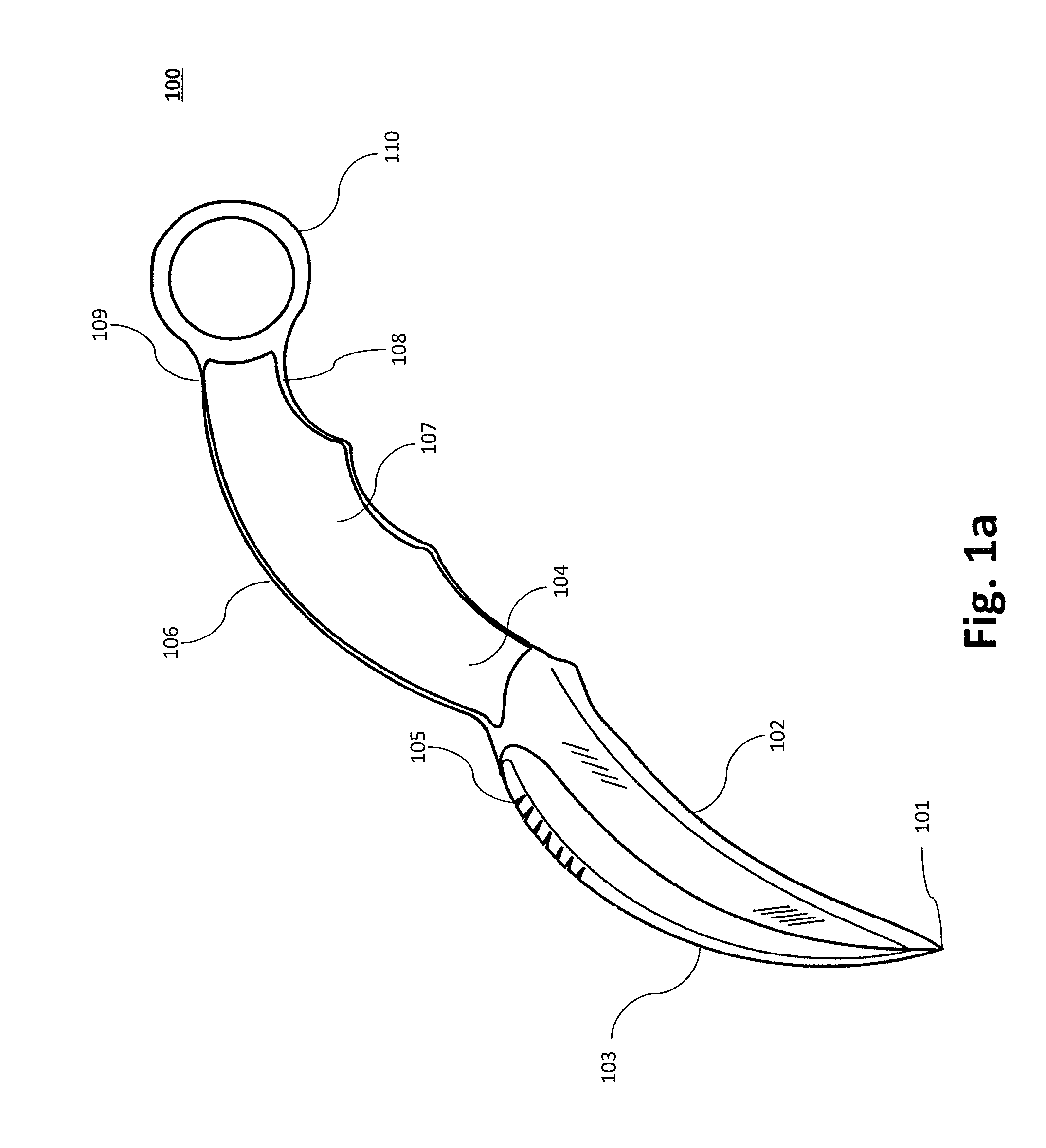
[0063]FIG. 4a illustrates an example of a novel folding straight edge karambit 400 with the added novel features, which include the mid-lock portion 201, the reverse lock portion 202, the thumb lock portion 203, and the knuckle portion 204 as described with regard to FIGS. 2a through 2h.

[0064]As will be appreciated from the figures, the straight edge karambit 200b and the folding straight edge karambit 400 share a number of correspondingly numbered components, which are described above and therefore will not be described in connection with the folding straight edge karambit 400. Thus, the tool, whether C-shaped, S-shaped, or the like, may be fabricated using a movably coupled discontinuation material or component. To facilitate folding, for example, the blade portion 207 is configured to pivot, with regard to the spine 206 (or handle 214), about a pivoting component 404. The pivoting component 404 may be, for example, a screw, rivet, or other shaft that enables the blade portion 20...


PUM


Abstract

A bladed apparatus comprising: a tool having (1) a first end; (2) a second end; and (3) a spine positioned between said first end and said second end, and a handle portion configured to hold said tool, said handle portion being located between said safety ring portion and said blade portion. A safety ring portion may be positioned at the first end, and a blade portion may be positioned at the second end, with the blade portion comprising an inside edge, an outside edge, and a point. The safety ring portion may comprise, along its outer periphery, (a) a mid-lock portion; (b) a thumb lock portion; and (c) a reverse lock portion.

Description

CROSS-REFERENCE TO RELATED APPLICATIONS[0001]This application claims priority to U.S. Provisional Patent Application No. 61 / 938,926, filed on Feb. 12, 2014, entitled “Karambit with Features Allowing Better Gripping and More Effective Utilization,” by Robert Irvin, which is hereby incorporated by reference in its entirety.TECHNICAL FIELD[0002]The article described as set forth herein is a novel cutting apparatus, specifically a karambit, with novel features that allow the operator improved control and stability of the karambit in different positions and functions.BACKGROUND[0003]The karambit was originally developed in Asia as an agricultural implement designed to rake roots, gather threshing and plant rice. More recently, the western world discovered that the karambit would be useful for self-defense. Those modern-day karambits produced in the western world for use as weapons are generally based on a small variety of the karambit, which features a short blade and index finger ring.[...

Claims


Application Information

Patent Timeline
Patent Type & Authority Applications(United States)
IPC IPC(8): B26B3/00B26B1/02F41B13/00
CPCB26B3/00B26B1/02F41B13/00B26B9/00B26B27/007F41B13/08F41B15/08B25G1/102
Inventor IRVIN, ROBERT
Owner IRVIN ROBERT
Why Eureka
Eureka Blog
Learn More