Wheel Rim Retainer

a technology of wheel rims and retainers, which is applied in the direction of rims, vehicle components, transportation and packaging, etc., can solve the problems of vehicle collisions, driver loss of control of the vehicle, and high tire occurrence rate, so as to minimize the risk coefficient of tire occurrence, improve the supporting effect, and improve the driving safety

Active Publication Date: 2015-08-20
YANG GUIRONG +1
View PDF8 Cites 0 Cited by
  • Summary
  • Abstract
  • Description
  • Claims
  • Application Information

AI Technical Summary

Benefits of technology

[0016]Accordingly, the wheel rim retainer further comprises a plurality of tire engaging elements spacedly provided on an outer surface of the annular unit. In particular, the tire engaging elements are spacedly protruded on the outer surfaces of the hinged members. The tire engaging elements are engaged with the inner surface of the flat tire so as to prevent the tire being free-rotated around the wheel rim when the tire is deflated, especially during braking operation of the vehicle.
[0026]1. The structure of the present invention is rational, wherein the hinged members, the first end connecting member, and the second end connecting member can be made of rigid materials, so the present invention can provide a better supporting effect due to tire blowout, and further improve the driving safety, so as to minimize the risk coefficient of the tire. In other words, since the wheel well of the wheel rim is covered by the annular unit, the present invention can prevent the bead of the flat tire being fallen at the wheel well and the bead flange of the vehicle rim being exposed to run on the road surface.
[0027]2. The present invention provides the best engagement between with the bottom side of the wheel well and the well retainers after installation, so as to ensure the control the wheel rim by the driver, such as operating the braking system of the vehicle. In addition, the wheel rim retainer will prevent the free-rotation of the tire, via the tire engaging elements of the present invention, with respect to the wheel rim after the tire is blown out.
[0029]4. The present invention is easy to be disassembled and assembled through the movable engagement of the hinged member. Especially during transportation and storage, the present invention can be disassembled, so the volume of the present invention is reduced to facilitate the transportation.

Problems solved by technology

In such situation, the occurrence rates of flat tires for the vehicle will dramatically increase especially when driving at high speed.
For example, when the tire pressure is dramatically dropped due to a blowout or puncture during running, the driver will loss the control of the vehicle easily.
As a result, collision of vehicles may occur.
Seriously, the vehicle may be flipped over due to the flat tire.
Vehicle explosion may occur due to the sparks generated by the friction between the bead flange of the vehicle rim and the road surface.
However, it is difficult to mount the elastic band around the hub surface of the wheel rim A10 because the operator must apply relatively strong pulling force to pull two free ends of the elastic band together and to overcome the elastic force thereof.
More importantly, the inner surface of the tire may be cut by the elastic band, which may damage the tire.
However, if the elastic band is made of relative rigid material to support the beads of the tire, the installation of the elastic band will be difficult to band in curve configuration and to match with the hub surface.
If the elastic band is made of relative soft material for easy installation, the elastic band may not be strong enough to support the beads of the tire.
Furthermore, the wedges cannot be securely engaged within the wheel well A11, via any engagement structure, that the lateral movement of the elastic band will cause the misalignment of the annular fastener around the hub surface of the wheel rim A10.
Therefore, the annular fastener cannot ensure the basic supporting function due to a blowout and may also seriously damage the tire.

Method used


Image

  • Wheel Rim Retainer
  • Wheel Rim Retainer
  • Wheel Rim Retainer

Examples


Embodiment Construction

[0043]The following description is disclosed to enable any person skilled in the art to make and use the present invention. Preferred embodiments are provided in the following description only as examples and modifications will be apparent to those skilled in the art. The general principles defined in the following description would be applied to other embodiments, alternatives, modifications, equivalents, and applications without departing from the spirit and scope of the present invention.

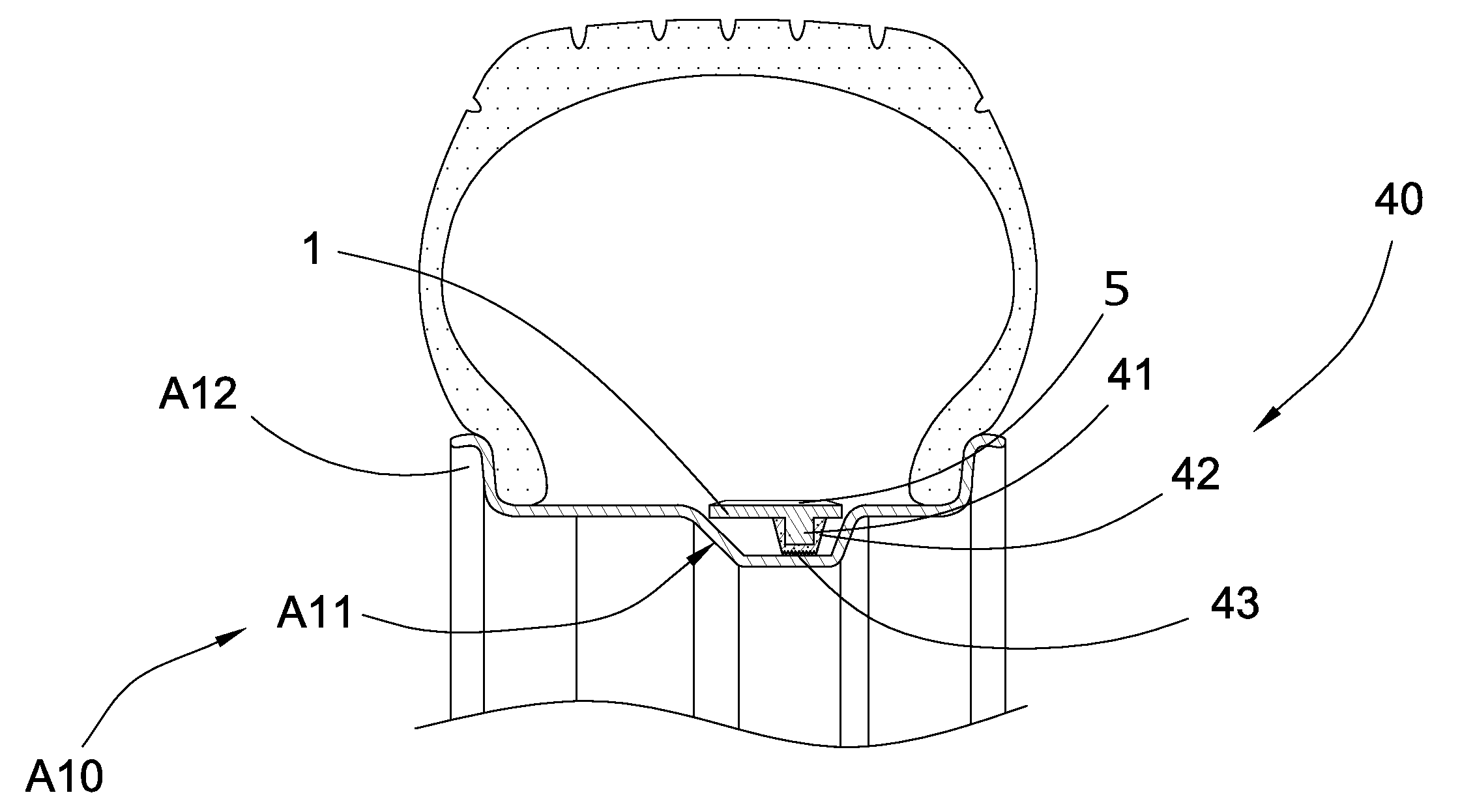
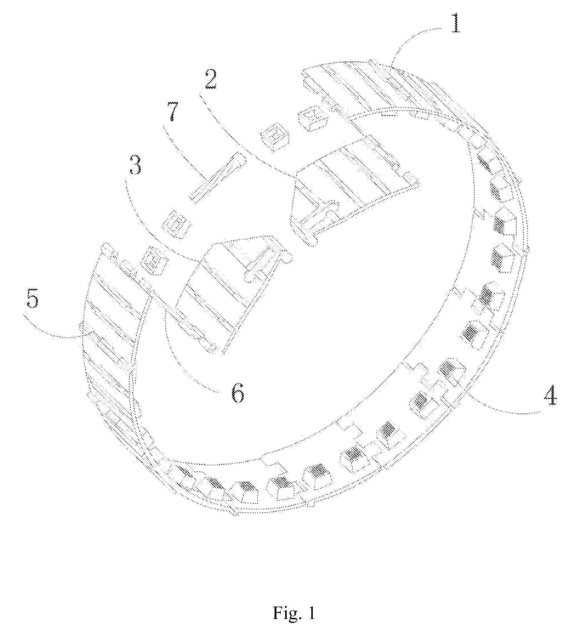
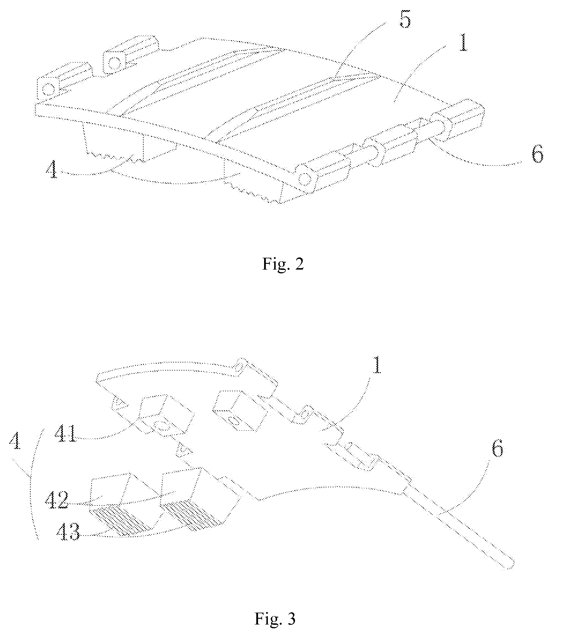
[0044]Referring to FIG. 1 to FIG. 6 of the drawings, a wheel rim retainer for use as a run-flat assembly and / or a bead-lock assembly according to a preferred embodiment of the present invention is illustrated, wherein the wheel rim retainer comprises an annular unit which comprises a plurality of hinged members 1 movably coupled with each other edge-to-edge, a first end connecting member 2 movably coupled at one end of the annular unit, and a second end connecting member 3 movably coupled at an o...


PUM


Abstract

A wheel rim retainer includes an annular unit, a first end connecting member movably coupled at one end of the annular unit, and a second end connecting member movably coupled at an opposed end of the annular unit. The annular unit includes a plurality of hinged members movably coupled with each other in an edge-to-edge manner, wherein each of the hinged members has a width larger than a width of the wheel well. The second end connecting member is detachably coupled with the first end connecting member for encircling the hinged members around a hub surface of a wheel rim to cover a wheel well thereof so as to prevent a bead of a tire falling at the wheel rim when the tire is deflated.

Description

NOTICE OF COPYRIGHT[0001]A portion of the disclosure of this patent document contains material which is subject to copyright protection. The copyright owner has no objection to any reproduction by anyone of the patent disclosure, as it appears in the United States Patent and Trademark Office patent files or records, but otherwise reserves all copyright rights whatsoever.BACKGROUND OF THE PRESENT INVENTION[0002]1. Field of Invention[0003]The present invention relates to a vehicle wheel rim, and more particularly to a wheel rim retainer which comprises a plurality of hinged-members fastened around the vehicle wheel rim for use as a run-flat assembly and / or a bead-lock assembly.[0004]2. Description of Related Arts[0005]Pneumatic tires are commonly mounted on a wheel rim A10 at a position that two beads of the tire are mounted at two bead flanges of the wheel rim A10, as shown in FIG. 8. An annular wheel well A11 is generally formed on a circumferential hub surface of the wheel rim A10 ...

Claims


Application Information

Patent Timeline
Patent Type & Authority Applications(United States)
IPC IPC(8): B60B25/20
CPCB60B21/12B60B21/026B60B2900/523B60C17/041
Inventor YANG, GUIRONGQI, YINGJIE
Owner YANG GUIRONG
Why Eureka
Try Eureka