

Pneumatic tire
Active Publication Date: 2015-08-20
SUMITOMO RUBBER IND LTD
View PDF8 Cites 11 Cited by
- Summary
- Abstract
- Description
- Claims
- Application Information
AI Technical Summary
Benefits of technology
[0004]It is therefore, an object of the present invention to provide a pneumatic tire in which, by specifically confi
Problems solved by technology
In the case of the lug groove, however, there is a possibi
Method used
View moreImage
Smart ImageViewing Examples

Examples
 PUM
 Abstract
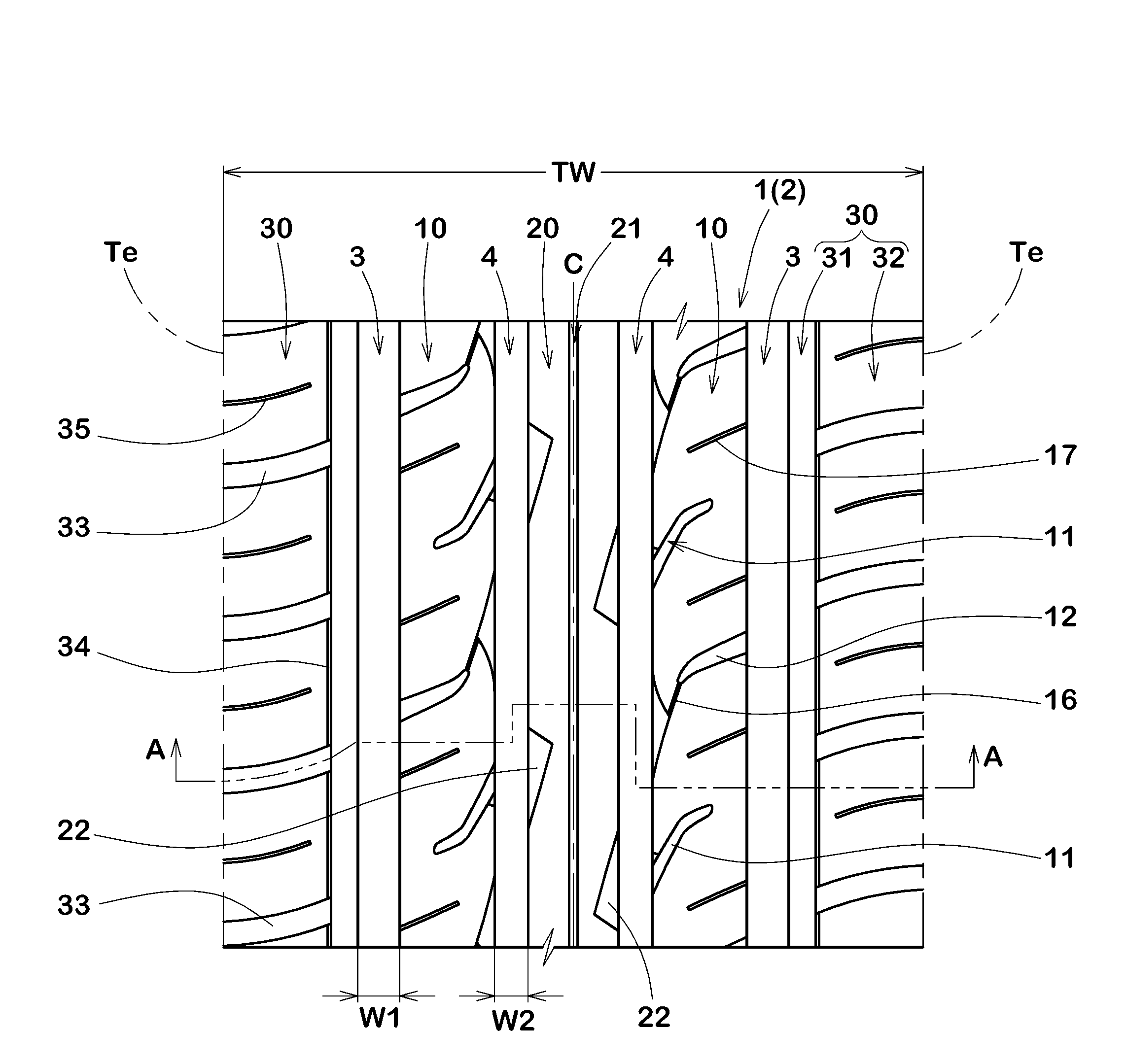
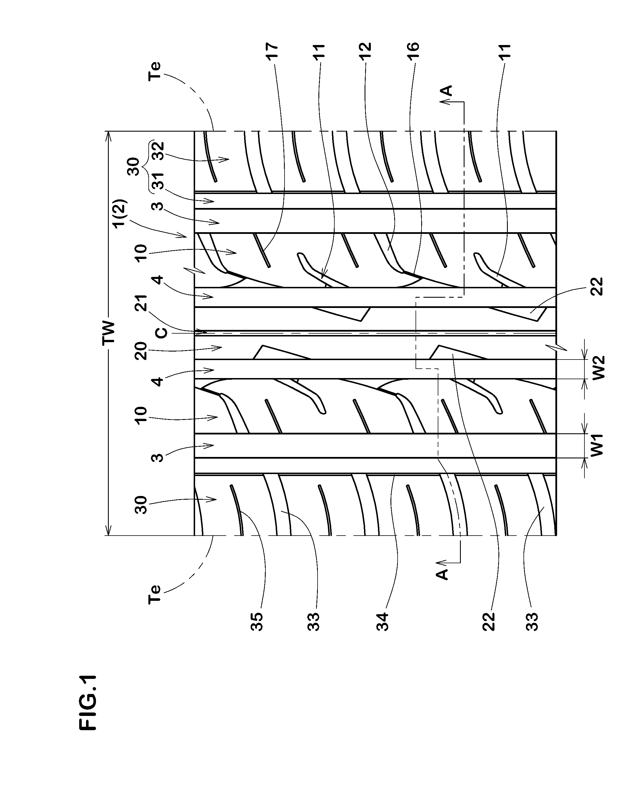
A pneumatic tire comprises a tread portion provided on each side of the tire equator with a middle land portion defined between a shoulder main groove and a crown main groove each extending continuously in the tire circumferential direction. The middle land portion is provided with axially inside middle lug grooves and axially outside middle lug grooves arranged alternately in the tire circumferential direction. The axially inside middle lug groove is connected to the crown main groove at an angle θ1 of from 20 to 45 degrees with respect to the tire circumferential direction and has an axially inner opened end and an axially outer closed end. The outside middle lug grooves is connected to the shoulder main groove at an angle θ2 of from 60 to 80 degrees with respect to the tire circumferential direction and has an axially outer open end and an axially inner closed end. The tread portion may be provided with a shoulder land portion comprising circumferential sipes, axial grooves terminating at the circumferential sipes, and a circumferentially continuous rib.
Description
BACKGROUND OF THE INVENTION[0001]The present invention relates to a pneumatic tire, more particularly to a tread pattern capable of satisfying both of wet performance and steering stability.[0002]Japanese Patent Application Publication Nos. 2012-188080 and 2010-132181 each disclose a pneumatic tire provided in the tread portion with lug grooves, wherein the lug groove is defined as having an end opened to a main groove or wide circumferential groove and another end terminating within a land portion in which the concerned lug groove is disposed.[0003]Such lug groove can maintain the rigidity of the land portion to improve the steering stability of the tire when compared with an axial groove whose both ends are opened to main grooves on both sides thereof. In the case of the lug groove, however, there is a possibility that the wet performance of the tire is deteriorated.Thus, the pneumatic tires disclosed in the above-mentioned patent documents have room for improvement to satisfy bot...
Claims
Login to View More Application Information
Patent Timeline
 IPC IPC(8): B60C11/03B60C11/12
CPCB60C11/03B60C11/1259B60C11/1272B60C11/12B60C2011/0341B60C2011/0386B60C2011/0381B60C11/0306B60C11/1369B60C11/1392B60C11/0304B60C2011/0369B60C2011/0383B60C2011/0348B60C2011/0344B60C2011/039B60C2011/0388B60C2011/0372B60C2011/0374B60C2011/0395
InventorSATO, TAKUYANAKAYAMA, HIROYUKI
OwnerSUMITOMO RUBBER IND LTD