

Bit Holder Shank and Differential Interference Between the Shank Distal Portion and the Bit Holder Block Bore
a technology of bit holder and distal portion, which is applied in the direction of cutting machines, ways, constructions, etc., can solve the problems of longer rotation time, more difficulty, and inability to rota
- Summary
- Abstract
- Description
- Claims
- Application Information
AI Technical Summary
Benefits of technology
Problems solved by technology
Method used
Image

Examples
first embodiment
The First Embodiment Bit Assembly
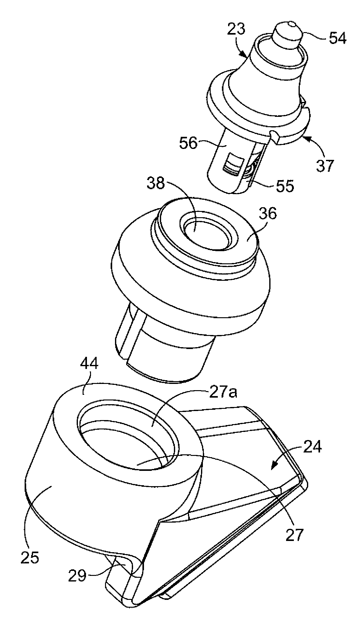
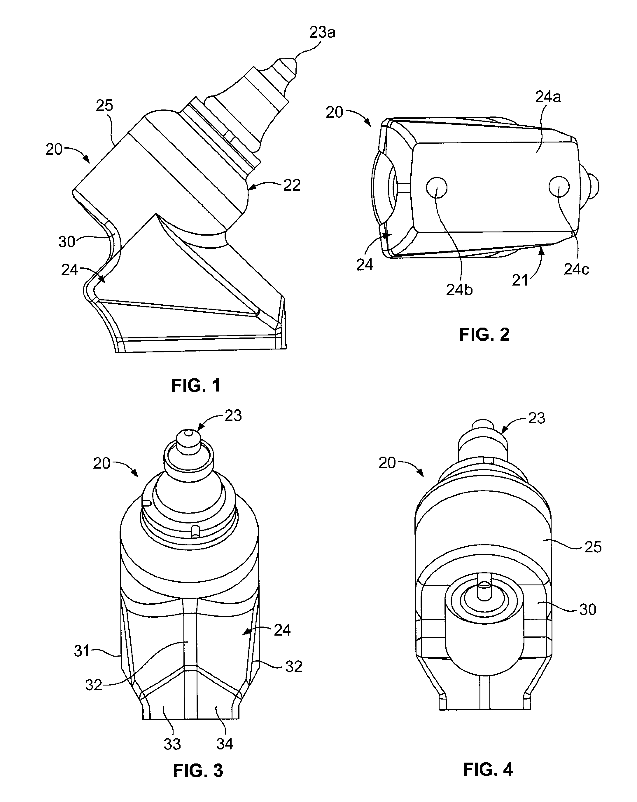
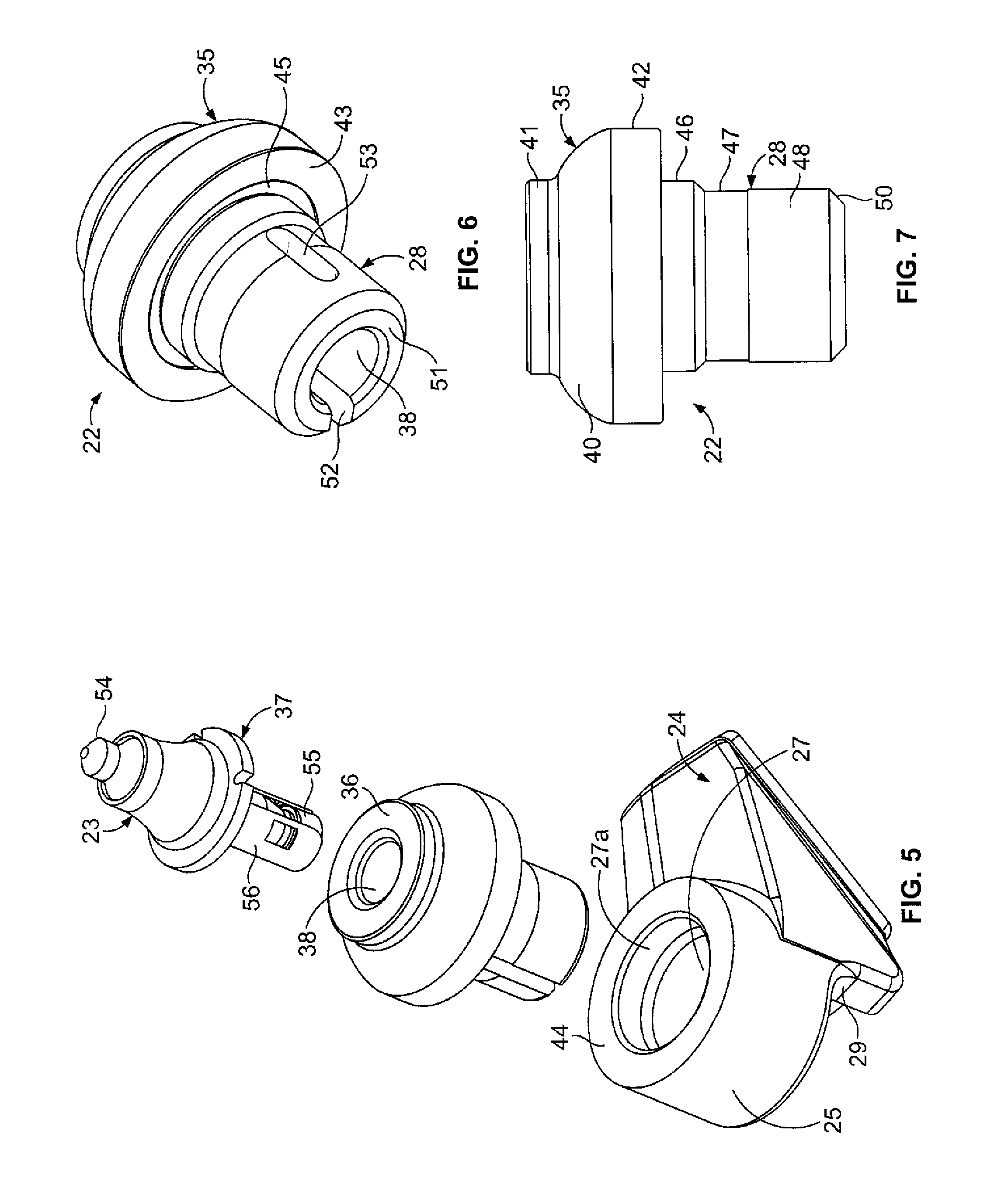
[0029]Each bit assembly 20 includes a bit holder block 21 having a base 24 and a bit holder or bit / holder mounting portion 25. In this embodiment, the bit holder mounting portion 25 is generally cylindrical and extends from the base 24 portion as mentioned previously. The bit block 21, constructed in accordance with the present invention, includes an axially shortened annular bit holder mounting portion 25 which receives the bit holder 22 or bit / holder (26, 26a FIGS. 8 and 15) in a bit block bore 27 positioned centrally therein. The shortened axial length of the generally annular bit holder holder receiving portion 25 approximates 1.5 inches in length with a nominal diameter of 1.5 inches (FIG. 7). The ratio of bit holder shank diameter D, bit holder mounting position, to its length L is generally a one to one ratio.
[0030]As shown most clearly in FIG. 11, the shortened shank can use an improved structure for either selectably releasing or securing th...
second embodiment
A Second Embodiment
[0044]Referring to FIGS. 8, 9 and 10, a second embodiment 20a of the invention is shown and described. This second embodiment includes a bit holder block 24 identical to that shown in the first embodiment. However, it also includes a unitary bit / bit holder 26a that has a base 57 with a body portion 58 from the lower part of which a shank 60 axially extends. This body portion 58 and shank 60 are substantially identical to the body portion 35 and shank 28 of the first embodiment of the present invention. However, the uppermost face of the central portion of the body includes an annular recess 61 from which a tapered annular distal portion axially extends. The combination of the outer surface of the distal tapered portion 62 and the annular recess 61 provides a base surface for mounting an annular tungsten carbide ring 63 which is a hollow frustoconical shape tapering from its bottom to the top thereof and snugly fitting over the distal annular portion of the body. T...
third embodiment
A Third Embodiment
[0047]Referring to FIGS. 12, 13 and 14, a third embodiment 70 of a bit holder is shown. This third embodiment 70 also includes an upper body portion 71 and a lower shank 72 portion. A first modification 73 of the third embodiment is shown in FIG. 14, to be discussed in more detail below. In each, the upper body portion 71 of the bit holder is substantially identical to the upper body portion of the first embodiment bit holder shown in FIGS. 1, 3, 5, 6 and 7. Also, the upper portion 74 and center portion 75 of the shank of this embodiment is identical to that shown in the first embodiment 20, specifically FIGS. 5, 6 and 7 thereof. However, the difference between the first embodiment 20 and this third embodiment 70 is found in a specific reverse non-locking taper of the distal portion 76 of the shank (as shown in the drawing). This non-locking size reverse taper fits in either cylindrical, or the preferred one degree per side regular taper of the bit holder block bor...
PUM
 Abstract
Description
Claims
Application Information