
Kinetic fireball incendiary munition

a technology of incendiary munition and fireball, which is applied in the direction of projectiles, weapons, ammunition projectiles, etc., can solve the problems of unintended and undesirable effects of harmful materials in collateral regions, no conventional munitions achieve such objects, and approaches that fail to raise the temperature of target volume to a high temperatur

Active Publication Date: 2015-08-27
EXQUADRUM
View PDF16 Cites 1 Cited by
  • Summary
  • Abstract
  • Description
  • Claims
  • Application Information

AI Technical Summary

Benefits of technology

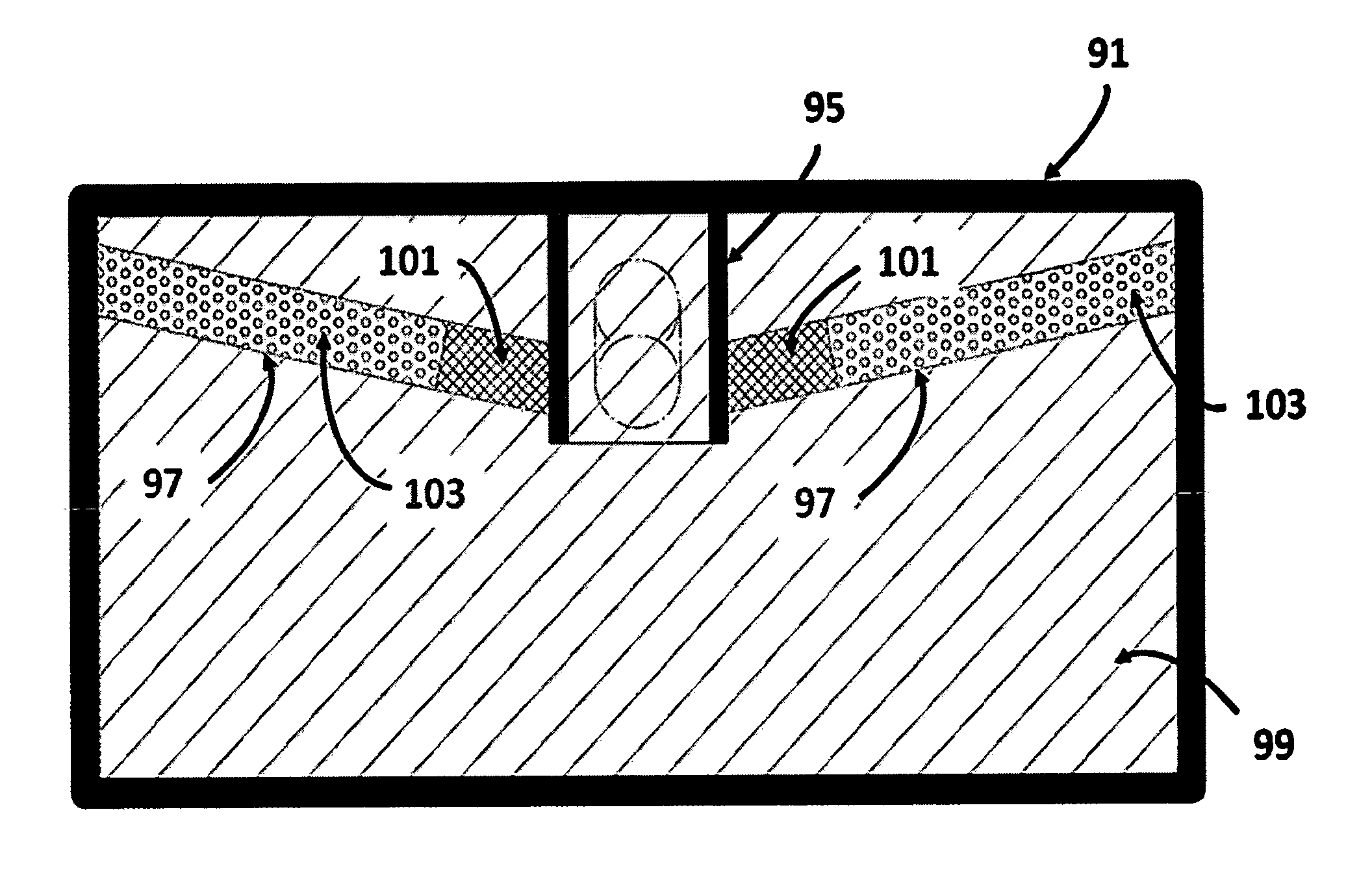
This patent describes a submunition that contains an internal oxidizer for both the incendiary portion and the rocket motor, allowing for ignition and heating from both surfaces. This results in a thermalization of the target structure without creating a significant overpressure or explosion. The submunition also has an insulation layer made of rubber or other foam materials filled with silica particles, which helps to prolong its survival in high-temperature environments. The technical effect of this patent is a more efficient and effective submunition for use in various applications.

Problems solved by technology

However, there is no disclosure in Bessey, et al. of an incendiary composition which can penetrate a structure and once inside can release sufficient heat to thermalize the environment to a high enough temperature to neutralize chemical and biological agents inside the target structure.
At present, no conventional munitions achieve such object.
Another problem is that these conventional approaches fail to raise the temperature of the target volume to a high temperature for an extended period of time.
Instead, conventional approaches employ high explosives with phosphorous, which generally raise the temperature of the target volume to high temperatures, but for only a fraction of a second and, in the process, cause an undesirable overpressure, which may destroy the vessels containing the materials and the structure resulting in the spread harmful materials into collateral regions, or into the atmosphere in an unintended and undesirable way.
Moreover, these conventional approaches also fail to transfer the necessary high heat uniformly through multi-rooms, halls, and large target volumes containing the materials to be destroyed.
One of the problems with this conventional type of incendiary munition is that it does not burn for a sufficient time to raise the overall temperature in a target room to temperatures sufficient to neutralize chemical and biological agents.

Method used


Image

  • Kinetic fireball incendiary munition
  • Kinetic fireball incendiary munition
  • Kinetic fireball incendiary munition

Examples


Embodiment Construction

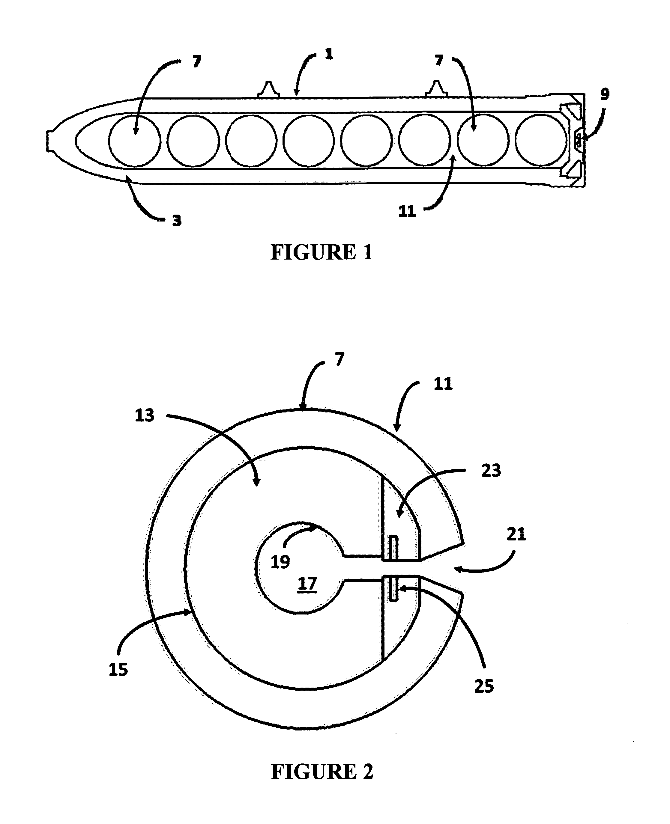
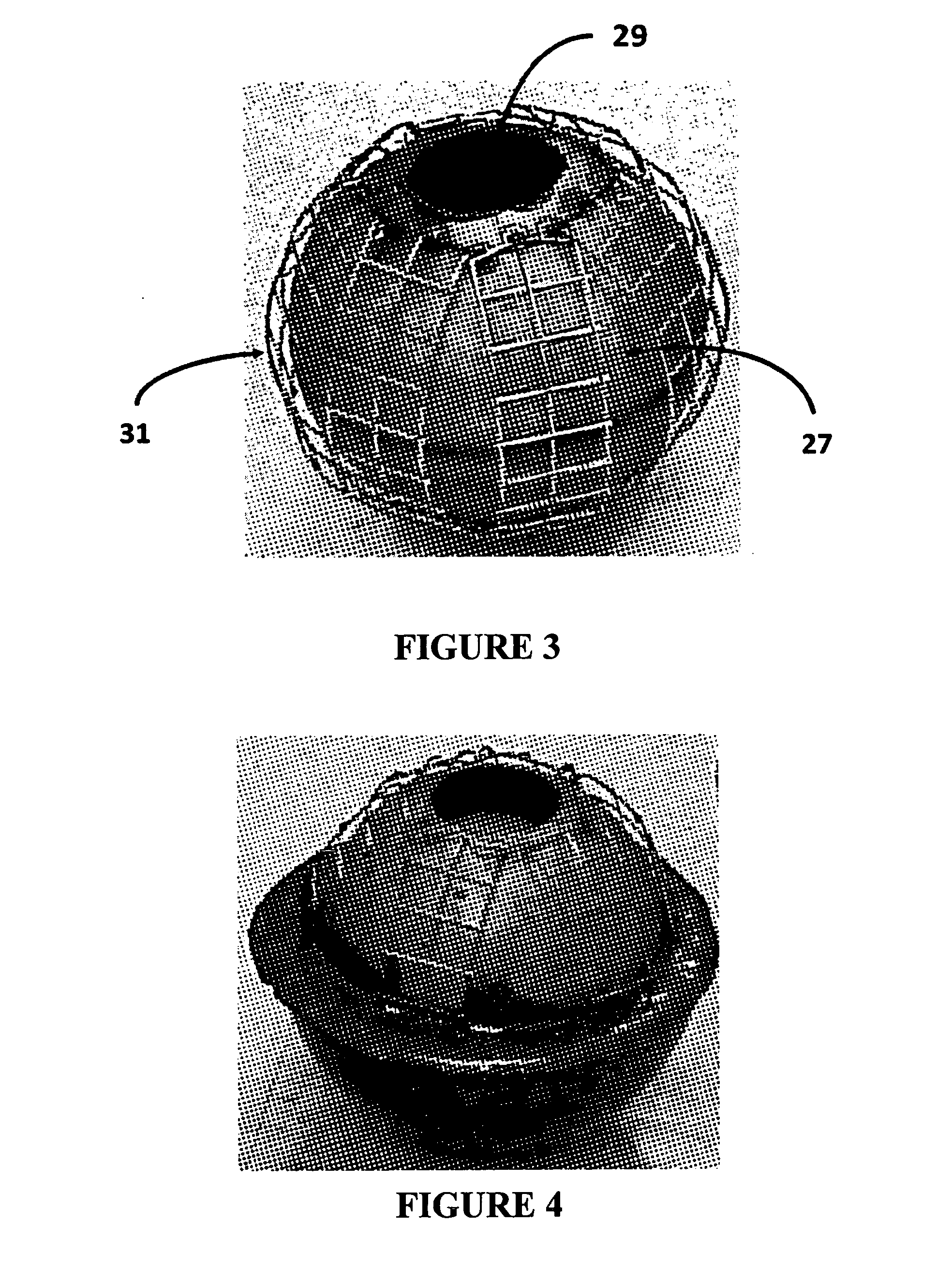
[0074]The present invention provides an incendiary munition comprised of an outer shell or bomb casing, one or more incendiary submunitions therein, and an igniter therefore. The incendiary submunition comprises an incendiary portion, and at least one rocket motor that fires when the incendiary portion ignites. It was unexpectedly discovered that, during operation, the combustion of the surface of the incendiary portion comprised of solid propellant creates a gas cushion that results in the levitation of the incendiary submunition above the ground.

[0075]While being levitated by the combustion of the outer surface of the incendiary submunition, the rocket motor disposed within the submunition ignites and propels the submunition and the incendiary portion violently around within the target structure. The combustion of the surface of the incendiary submunition, along with the firing of the rocket motor therein, liberates sufficient heat to produce elevated temperatures inside of a targ...


PUM


Abstract

A kinetic fireball incendiary munition is provided having an outer shell or bomb casing, one or more incendiary sub munitions therein, and an igniter therefore. Each of the submunitions includes an incendiary portion, at least one rocket motor that propels the submunition inside of a target volume, and an oxidizer for the incendiary portion and rocket motor. The submunitions liberate sufficient heat to produce elevated temperatures inside of a target structure to thermalize the contents thereof without creating a substantial overpressure or explosive effect.

Description

REFERENCE TO RELATED APPLICATIONS[0001]This is a continuation-in-part of U.S. patent application Ser. No. 11 / 804,412, filed May 18, 2007, now pending, which is a divisional of parent U.S. patent application Ser. No. 11 / 434,045, filed May 15, 2006, now U.S. Pat. No. 7,278,356 B1.FIELD OF THE INVENTION[0002]The present invention relates in general to incendiary munitions and, more particularly, to an incendiary munition capable of thermalizing the interior of targets, such as bunkers, buildings, gun emplacements, storage facilities, etc. to a high enough temperature to neutralize chemical and biological agents. Further, a disc-shaped incendiary submunition is provided having one or more barrels embedded in the incendiary material which contains a powder charge and projectile(s) which can be fired radially outwardly to damage any stored containers of chemical / biological materials.BACKGROUND OF THE INVENTION[0003]Modern warfare has been evolving in the direction of the use of precision-...

Claims


Application Information

Patent Timeline
Patent Type & Authority Applications(United States)
IPC IPC(8): F42B12/44
CPCF42B12/44F42B12/52F42B12/58
Inventor GEISLER, ROBERT L.MAHAFFY, KEVIN E.
Owner EXQUADRUM
Learn More