Monitoring camera system and control method of monitoring camera system

a camera system and camera technology, applied in the field of monitoring camera system and control method of monitoring camera system, can solve the problems of difficult to capture an image of a specific monitoring target area in the store, difficult to protect the privacy of the figure, and difficult to grasp

Inactive Publication Date: 2015-08-27
PANASONIC INTELLECTUAL PROPERTY MANAGEMENT CO LTD
View PDF4 Cites 23 Cited by
  • Summary
  • Abstract
  • Description
  • Claims
  • Application Information

AI Technical Summary

Problems solved by technology

For example, when the network camera captures an image of the specific commodity shelf in the store, an image of a figure existing in the vicinity of the specific commodity shelf may be captured, the display situation of the specific commodity shelf is concealed by the figure, and it may be difficult to protect privacy of the figure due to a reflection of the figure when a projected image of the display situation of the commodity shelf is captured (refer to FIG. 8A). FIG. 8A is a diagram illustrating an example of a situation in which it is difficult to grasp the display situation of the commodity shelf in a monitoring target area due to the reflection of the figure.
Thus, in the related art, it is difficult to capture an image of a specific monitoring target area in the store including the commodity shelf in a situation where the figure is not reflected even while monitoring the display situation of the commodity shelf at a wide range in the store.

Method used


Image

  • Monitoring camera system and control method of monitoring camera system
  • Monitoring camera system and control method of monitoring camera system
  • Monitoring camera system and control method of monitoring camera system

Examples


first exemplary embodiment

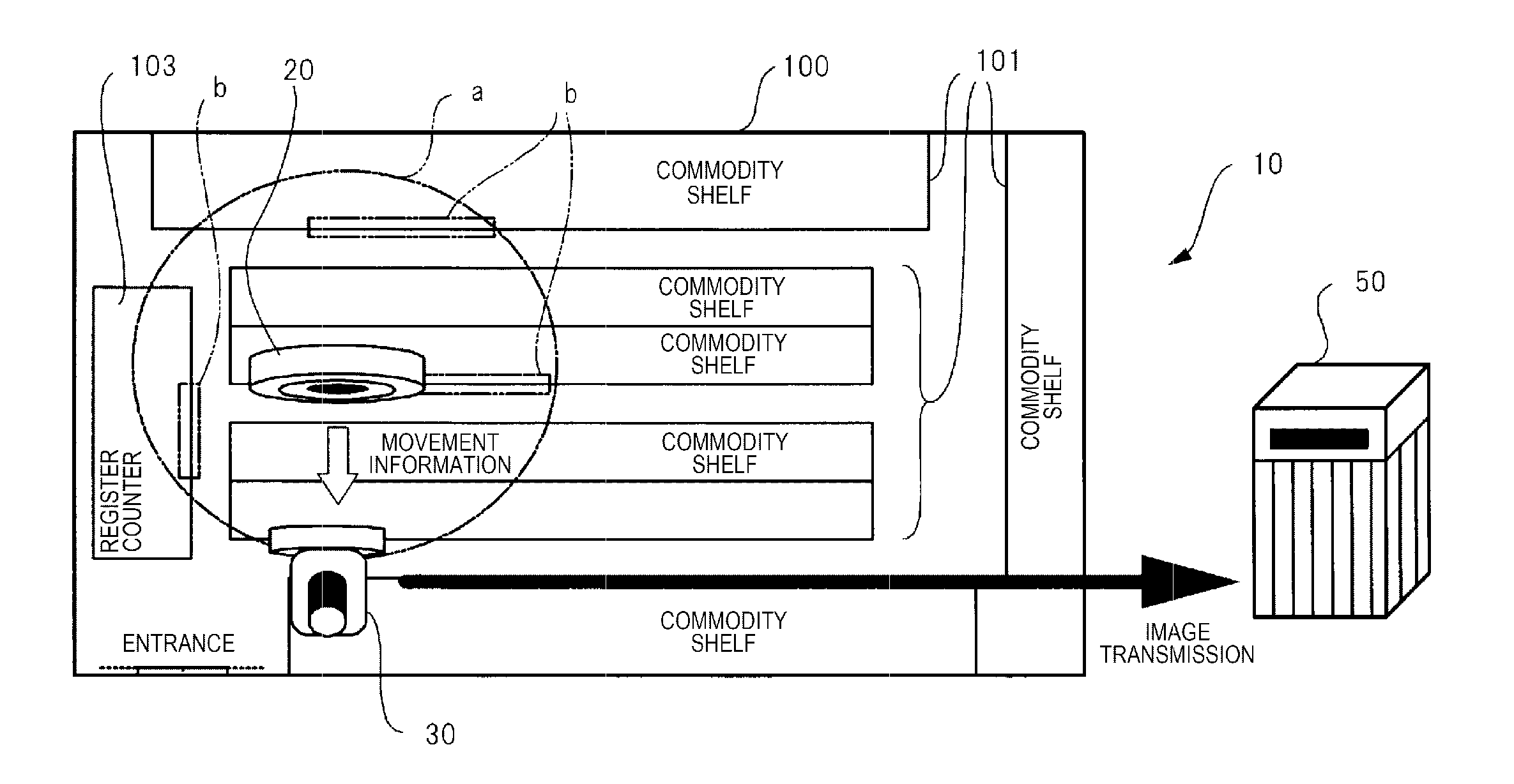
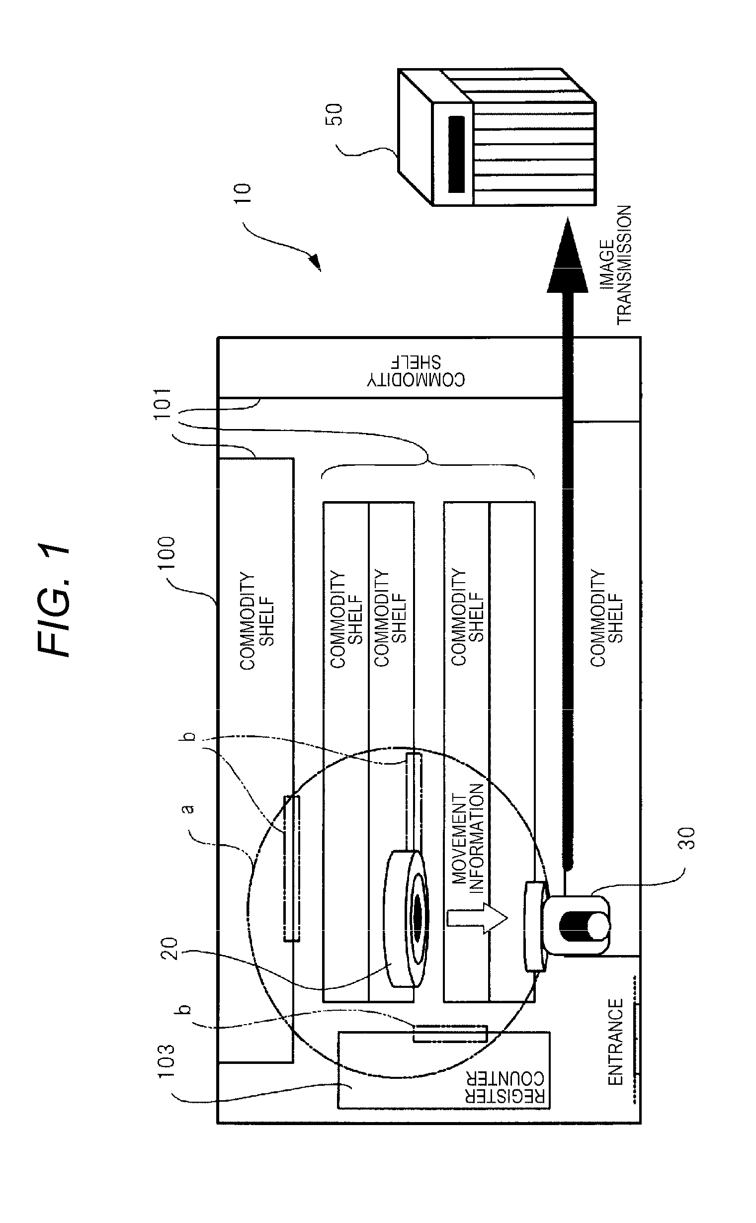
[0031]FIG. 1 is a schematic view illustrating an operation outline of monitoring camera system 10 of a first exemplary embodiment. Monitoring camera system 10 illustrated in FIG. 1 includes at least one image processing camera 20 and pan tilt zoom (PTZ) camera 30 which are disposed to be capable of capturing an image of commodity shelf 101, register counter 103, or the like in store 100. Image processing camera 20 and PTZ camera 30 of this embodiment are network cameras which are connected through a network to be capable of communicating with each other.

[0032]Image processing camera 20 is disposed on a ceiling surface of store 100, and is an omnidirectional camera which is able to capture an image at 360° from above in the store. For example, in image processing camera 20, a fixed field angle (a first field angle) is set such that an image of a monitoring target area in a circular range indicated by a symbol “a” in FIG. 1 is able to be captured. Furthermore, a field angle of image p...

modification example of first exemplary embodiment

[0087]FIG. 10 is a sequence diagram illustrating an operation procedure up to the image capture processing of the specific monitoring target area in monitoring camera system 10 of a modification example of the first exemplary embodiment. In the description illustrated in FIG. 10, the same reference numerals are used for the same operation as that in the description illustrated in FIG. 5, and thus the description thereof will be simplified or omitted, and different contents will be described. In the modification example of the first exemplary embodiment, even when the change in the field angle (the second field angle) is completed, PTZ camera 30 does not notify image processing camera 20 of the change completion notification.

[0088]Specifically, after the first movement information is notified to PTZ camera 30, as an example of a predetermined period of time, for example, when 6 seconds as a time which is assumed that PTZ camera 30 completes the change in the field angle in advance (h...

second exemplary embodiment

[0090]In the first exemplary embodiment described above, an example of a case where image processing camera 20 and PTZ camera 30 are connected in one-to-one is described. In a second exemplary embodiment, an example of monitoring camera system 10A in which a plurality of (for example, two) PTZ cameras 30A and 30B are connected to one image processing camera 20 is described. An image processing camera and a PTZ camera of the second exemplary embodiment have a configuration approximately identical to that of the first exemplary embodiment described above, and thus the description thereof will be simplified or omitted by using the same reference numerals or the corresponding reference numerals for the same constituents as that of the first exemplary embodiment.

[0091]FIG. 11 is a sequence diagram illustrating an operation procedure up to image capture processing of a specific monitoring target area in monitoring camera system 10A of a second exemplary embodiment. In the description of F...


PUM


Abstract

An image processing camera generates movement information on the basis of an omnidirectional image captured at a fixed field angle, and notifies PTZ camera of first movement information through a network. The PTZ camera analyzes the first movement information, changes a field angle to a specific monitoring target area. The image processing camera transmits second movement information to the PTZ camera. The PTZ camera analyzes the second movement information, captures a projected image of the specific monitoring target area when it is recognized that a current field angle is correct on the basis of the second movement information. Accordingly, an image of the specific monitoring target area is captured in a situation where there is no object such as a figure while monitoring a wide range.

Description

BACKGROUND OF THE INVENTION[0001]1. Field of the Invention[0002]The present invention relates to a monitoring camera system capturing a projected image of a predetermined monitoring target area and a control method of a monitoring camera system.[0003]2. Description of the Related Art[0004]In the related art, a monitoring camera system monitoring inside a store by using an omnidirectional camera disposed on a ceiling of the store or the like is known. As the related art relevant to such a monitoring camera system, for example, an image distribution device disclosed in Japanese Patent Unexamined Publication No. 2004-208214 is known.[0005]The image distribution device periodically receives an image inside the store which is captured by a network camera, and differentiates whether a figure is reflected on the received image. The image distribution device distributes the image which is differentiated in that the figure is not reflected to a Web server.[0006]The network camera disclosed i...

Claims


Application Information

Patent Timeline
Patent Type & Authority Applications(United States)
IPC IPC(8): H04N7/18
CPCH04N7/181G08B13/19608H04N23/661H04N23/698H04N23/695H04N23/90
Inventor NODA, JUNKOHOSOI, KOSUKETANAKA, AKINOBUSHIMIZU, TOSHIHIRO
Owner PANASONIC INTELLECTUAL PROPERTY MANAGEMENT CO LTD
Why Eureka
Try Eureka