Wireless communication method and wireless communication system

a wireless communication and wireless communication technology, applied in the field of wireless communication methods and wireless communication systems, can solve the problems of difficult to achieve a long transmission distance, large transmission loss, and further large transmission loss, and achieve the effect of difficult to prevent interference between adjacent channels

Inactive Publication Date: 2015-09-03
PANASONIC CORP
View PDF7 Cites 45 Cited by
  • Summary
  • Abstract
  • Description
  • Claims
  • Application Information

AI Technical Summary

Benefits of technology

[0013]In a case where communication is performed between a plurality of base stations and a plurality of terminal stations using a plurality of channels at the same time, there is a possibility that interference occurs between adjacent channels. However, in the conventional method of beam forming training, an optimum beam number is selected by the base station based on the communication quality in communication with the terminal station via a single channel, and thus it is difficult to prevent interference between adjacent channels.
[0018]One non-limiting and exemplary embodiment provides a wireless communication method capable of suppressing interference between adjacent channels even when communication is performed simultaneously between a plurality of base stations and a plurality of terminal stations using a plurality of channels, thereby making it possible to achieve high-quality communication.
[0019]In one general aspect, the techniques disclosed here feature that a wireless communication method for performing communication between a respective plurality of base stations and a corresponding plurality of terminal stations, each base station having a plurality of beams and being capable of switching the plurality of beams, the method including selectively switching a combination of beams used by the respective base stations among a plurality of combinations of beams and transmitting, synchronously and sequentially, training frames to the plurality of terminal stations, storing information representing the plurality of combinations of beams for the plurality of base stations based on a result of reception of the training frames, and selecting, from the stored information representing the combinations of beams for the plurality of base stations, a combination of beams that provides a best overall performance of the plurality of base stations, and allowing it to perform communication to be performed between the plurality of base stations and corresponding terminal stations.
[0020]Thus the present disclosure provides makes it possible to suppress interference between adjacent channels even when communication is performed simultaneously between a plurality of base stations and a plurality of terminal stations using a plurality of channels, thereby making it possible to achieve high-quality communication.

Problems solved by technology

In the communication using a millimeter wave, by nature of its extremely high frequency, a large transmission loss occurs.
Furthermore, its nature of propagating straight results in a further large transmission loss in non line of sight communication, which makes it difficult to achieve a long transmission distance.
In a case where communication is performed between a plurality of base stations and a plurality of terminal stations using a plurality of channels at the same time, there is a possibility that interference occurs between adjacent channels.
However, in the conventional method of beam forming training, an optimum beam number is selected by the base station based on the communication quality in communication with the terminal station via a single channel, and thus it is difficult to prevent interference between adjacent channels.
Therefore, when the conventional method of beam forming training is used, there is a possibility that it is difficult to achieve high-quality communication.
There is an area in which overlapping occurs between the communication area of the pair #1 and the communication area of the pair #2, and thus interference may occur in this area.
However, in a case where the beam determined by the terminal station 101-1 as the optimum beam based on the result of the beam forming training is a beam that causes interference with communication of the pair #2 and thus that is improper for actual use in communication, it is difficult to perform communication using channel Ch1 or the channel Ch2.

Method used


Image

  • Wireless communication method and wireless communication system
  • Wireless communication method and wireless communication system
  • Wireless communication method and wireless communication system

Examples


embodiments

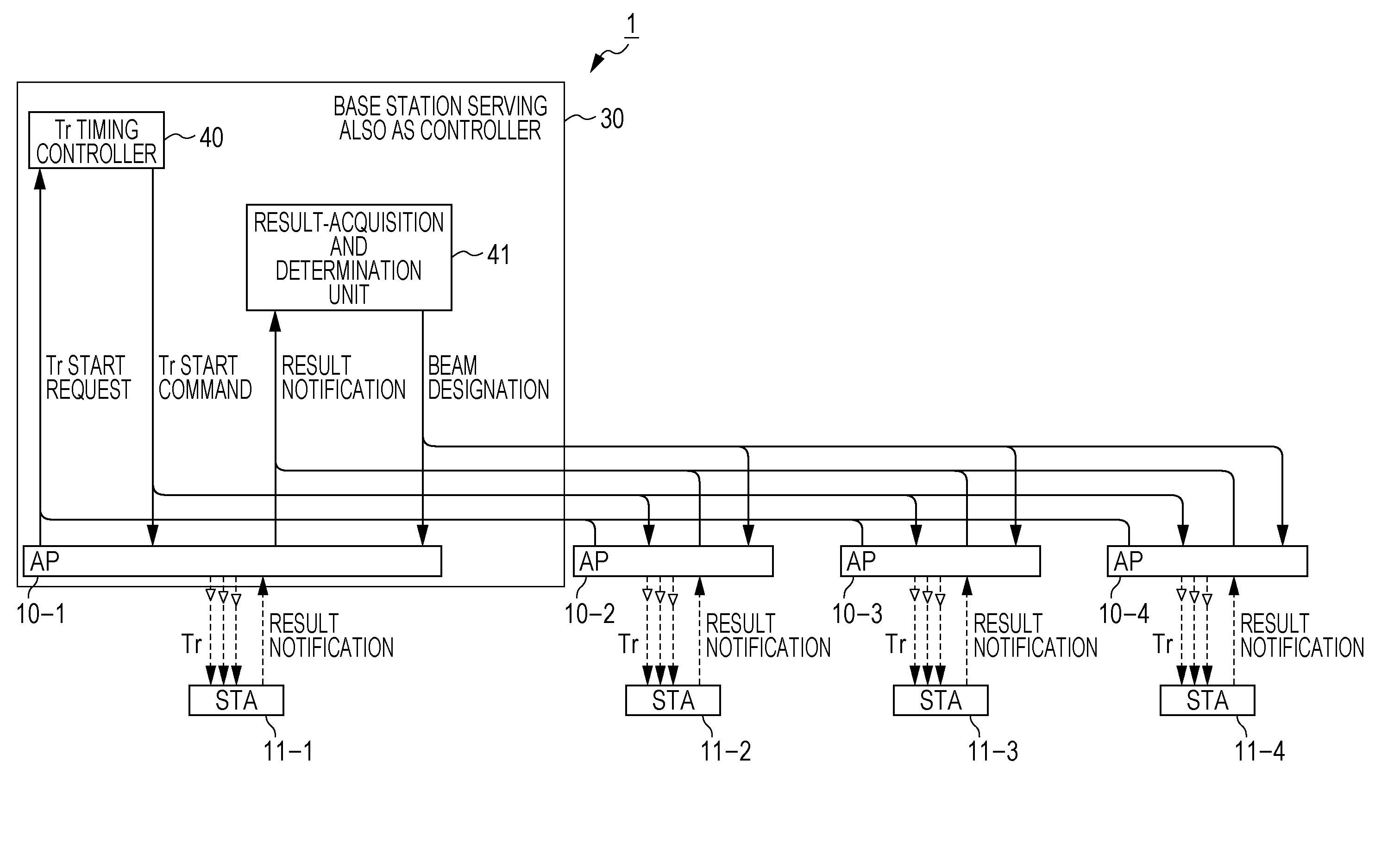
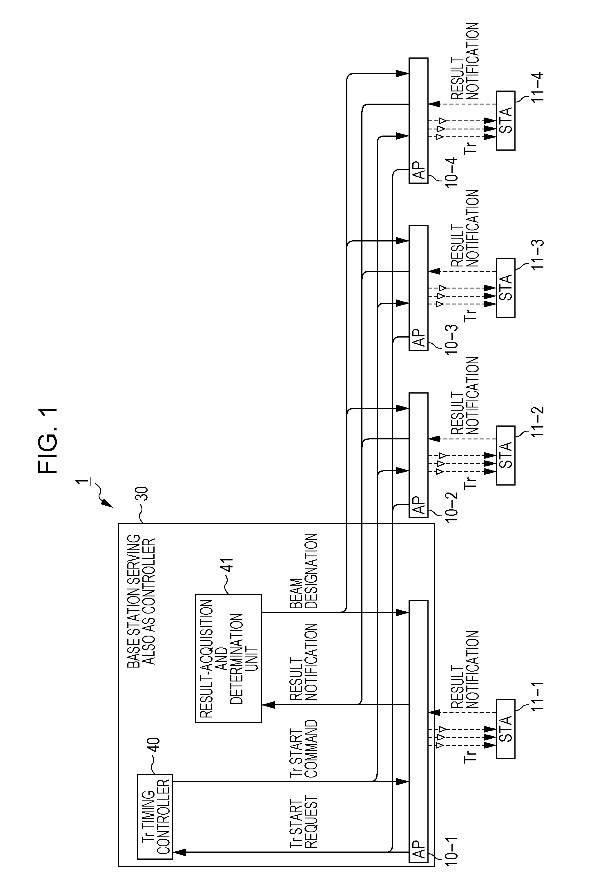
[0066]FIG. 1 is a block diagram illustrating a configuration of a wireless communication system according to an embodiment. In FIG. 1, the wireless communication system 1 according to the embodiment operates by using mainly a frequency band equal to or higher than the millimeter wave, and communication is allowed between respective four base stations 10-1 to 10-4 each having three beams and being capable of switching the three beams and corresponding four terminal stations 11-1 to 11-4. Of the four base stations 10-1 to 10-4, the base station 10-1 includes a unit (a control unit) that performs beam forming training between the four base stations 10-1 to 10-4 including the base station 10-1 itself and the four terminal stations 11-1 to 11-4 and sets optimum beams for the respective four base stations 10-1 to 10-4.

[0067]The base station 10-1 includes a control unit 30 including a Tr timing controller 40 and a result-acquisition and determination unit (corresponding to a storage unit, ...

third example

of Application

[0113]A base station may command terminal stations and base stations to perform transmission beam forming training sequentially in the order from the terminal stations to the base stations. In this specific example, Grant frames are used to send a start request, and Ransack frames are used to send a start command. FIG. 16 and FIG. 17 are diagrams illustrating a method of performing beam forming training in the wireless communication system 1 according to the third example of an application of the embodiment. This method is useful, for example, in a case where a terminal station triggers the start of the beam forming training when the terminal station detects degradation in communication quality.

fourth example

of Application

[0114]After the combination of transmission beams is determined taking into account the state of interference via the procedure described above, reception beam forming training may be performed at each base station and terminal station. FIGS. 18 to 21 are diagrams illustrating examples of methods of performing beam forming training in the wireless communication system 1 according to the fourth example of an application of the embodiment.

[0115]In the following description with reference to FIGS. 18 to 21, it is assumed by way of example that there are three base stations and three terminal station, and three channels are used. Note that the beam forming training may be performed in a similar manner and similar effects may be obtained also in a case where there are four base stations and four terminal stations and four channels are used.

[0116]In the example illustrated in FIG. 18, the combination of beams on the transmission side (the base stations) is fixed and the comb...


PUM


Abstract

A wireless communication method for performing communication between a respective plurality of base stations and a corresponding plurality of terminal stations, each base station having a plurality of beams and being capable of switching the plurality of beams, including selectively switching a combination of beams used by the respective base stations among a plurality of combinations of beams and transmitting, synchronously and sequentially, training frames to the plurality of terminal stations, storing information representing the plurality of combinations of beams for the plurality of base stations based on a result of reception of the training frames, and selecting, from the stored information representing the combinations of beams for the plurality of base stations, a combination of beams that provides a best overall performance of the plurality of base stations, and allowing it to perform communication to be performed between the plurality of base stations and corresponding terminal stations.

Description

BACKGROUND[0001]1. Technical Field[0002]The present disclosure relates to a wireless communication method and a wireless communication system.[0003]2. Description of the Related Art[0004]It is known to perform wireless communication using a millimeter wave in a frequency range from 30 GHz to 300 GHz. For example, in Japan, four channels are assigned at 58.32 GHz, 60.48 GHz, 62.64 GHz, and 64.80 GHz (each represented by center frequency) in a 60 GHz band. FIG. 24 is a diagram illustrating frequencies assigned to the respective channels in the 60 GHz band.[0005]Standards for wireless communication using the 60 GHz band include, for example, IEEE (The Institute of Electrical and Electronics Engineers, Inc.) 802.11ad (see, for example, IEEE802.11ad-2012). This wireless communication standard supports wireless transmission at a transmission rate higher than Gbps, which may be used, for example, to transfer a file from a terminal to a television set, transmit image data, or the like, or m...

Claims


Application Information

Patent Timeline
Patent Type & Authority Applications(United States)
IPC IPC(8): H04W16/28H04B15/00
CPCH04B15/00H04W16/28H04B7/0695
Inventor IRIE, MASATAKAURABE, YOSHIO
Owner PANASONIC CORP
Why Eureka
Try Eureka