Modular turbomachine inner and outer casings with multi-stage steam extraction sites

Inactive Publication Date: 2015-09-10
GENERAL ELECTRIC CO
View PDF4 Cites 4 Cited by
  • Summary
  • Abstract
  • Description
  • Claims
  • Application Information

AI Technical Summary

Benefits of technology

[0007]A third aspect provides a method of fabricating a turbomachine casing structure, the method comprising: forming a casing inner shell having an external surface, wherein a material of the casing inner shell defines an inner shell cavity and a fluid opening for allowing fluid from a turbomachine steam path to enter the inner shell cavity; and forming a casing outer shell having an internal surface such that the internal surface of the outer shell and the external surface of the inner shell define at least one closed chamber extending in an axial direction of the steam turbomachine; forming, in the casing inner shell, a first access region adjacent the at least one closed chamber, the first access region including a plurality of inner shell axial locations, wherein at least one of the plurality of inner shell axial locations is selectable to be machined to create an exhaust slot for allowing fluid to exit the inner shell cavity and enter the at least one closed chamber, and wherein a structural integrity of the casing is uniform regardless of which of the inner shell axial locations is selected to be machined; and forming, in the casing outer shell, a second access region adjacent the at least one closed chamber, the second access region including a plurality of outer shell axial locations, wherein at least one of the plurality of outer shell axial location is selectable to be machined to create an exhaust opening fluidly connected with the at least one closed chamber through the outer shell and wherein the structural integrity of the casing is uniform regardless of which of the outer shell axial locations is selected to be machined.

Problems solved by technology

Also, the site of extraction of the fluid affects the operation of the turbomachine itself.

Method used


Image

  • Modular turbomachine inner and outer casings with multi-stage steam extraction sites
  • Modular turbomachine inner and outer casings with multi-stage steam extraction sites
  • Modular turbomachine inner and outer casings with multi-stage steam extraction sites

Examples


Embodiment Construction

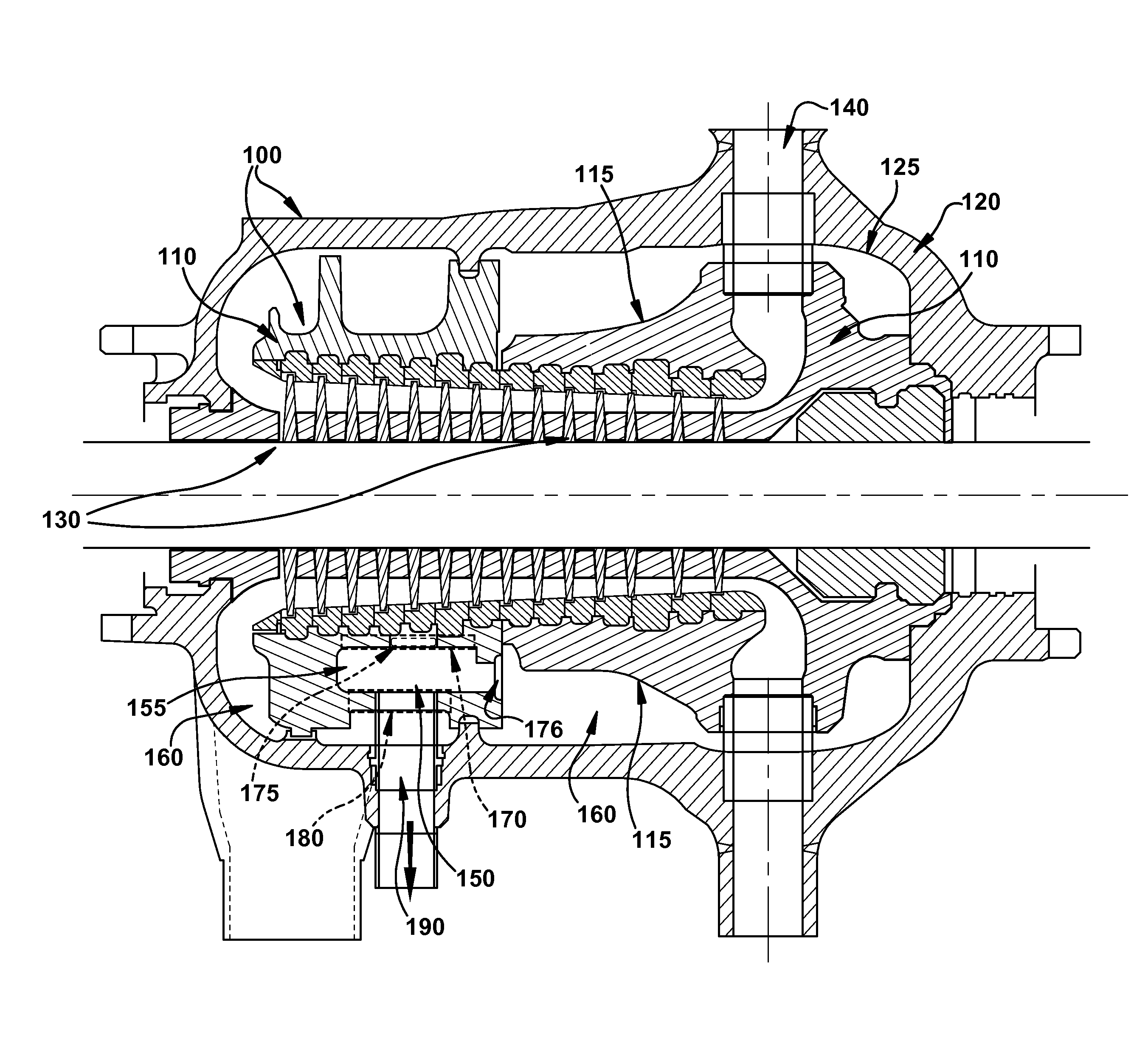
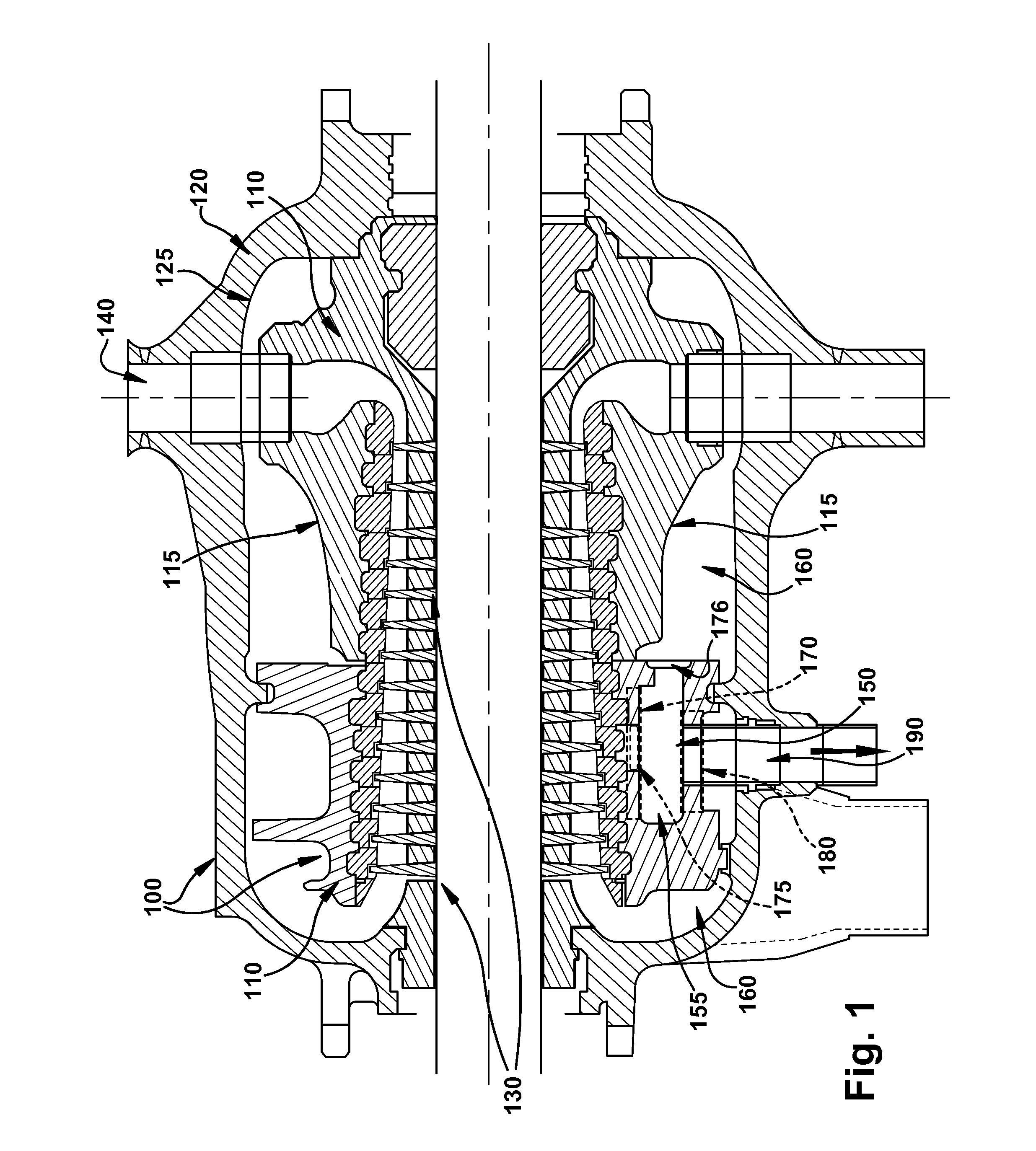
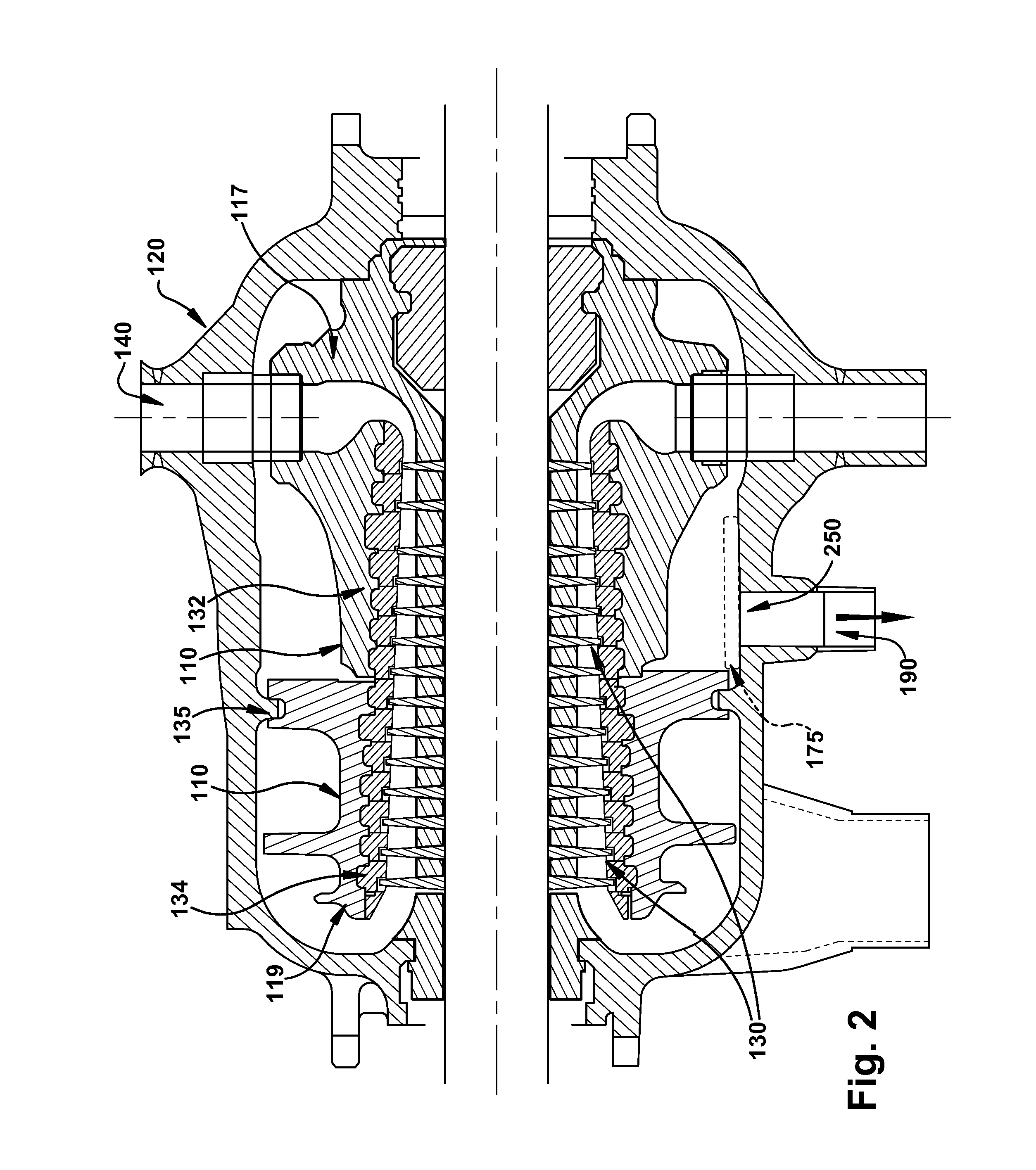
[0017]The subject matter disclosed herein relates generally to steam turbines. More specifically, the disclosure provided herein relates to inner and outer casings within steam turbines.

[0018]As indicated herein, illustrative embodiments of turbomachine casing intermediate structures and methods of their manufacture are disclosed. Embodiments described herein include turbomachine intermediate structures having many different possible fluid extraction locations which may be selected to be machined after desired characteristics of extractable fluid are known. Intermediate structures may be produced in order to be adapted at a later date. That is a casing intermediate structure may be produced with a plurality of locations for potential steam extraction, however none of such steam extraction locations are machined to define fluid extraction ports or openings in an intermediate structure. Intermediate structures are useful because a single, modular design may be modified in many differe...


PUM

PropertyMeasurementUnit
pressureaaaaaaaaaa
thicknessaaaaaaaaaa
timeaaaaaaaaaa

Abstract

Various embodiments include methods and apparatuses of forming turbomachine casing intermediate structures. In some embodiments apparatuses include a steam turbomachine casing intermediate structure including an inner shell having an external surface and inner shell cavity, and defining an opening for allowing fluid entry to the cavity and an outer shell having an internal surface, these surfaces defining at least one closed, axial-extending chamber, the inner shell and outer shells each having access regions adjacent the closed chamber, each of the access regions including a plurality of locations, selectable to be machined to create an exhaust slot or an exhaust opening in the inner casing or the outer casing, respectively, and wherein a structural integrity of the casing is uniform regardless of which of the axial locations are selected to be machined, where the exhaust opening is fluidly connected with the at least one closed chamber through the outer shell.

Description

FIELD OF THE INVENTION[0001]The subject matter disclosed herein relates generally to steam turbines. More specifically, the disclosure provided herein relates to inner and outer casings within steam turbines.BACKGROUND OF THE INVENTION[0002]There is often a need to extract fluid from a turboelectric machine in order to use the fluid for an industrial process. Turbomachine casings may be tapped in order to extract high pressure fluid circulating within and the high pressure fluid may be used for many different applications which may include powering an adjacent machine or heating water prior to its being used as steam. The location of fluid extraction from the turbomachine casing may be chosen based on characteristics of the high pressure fluid at such a location, i.e., fluid that is extracted through a port in an upstream stage of the turbomachine will have higher pressure than fluid that is extracted from a downstream stage. Also, the site of extraction of the fluid affects the ope...

Claims


Application Information

Patent Timeline
Patent Type & Authority Applications(United States)
IPC IPC(8): F01D9/06F01D25/26
CPCF01D25/26F01D9/065F01D25/24F01D25/32F05D2220/31F05D2230/21F05D2230/61Y10T29/49229
Inventor KOTIAN, DAYANANDA THUKRAAMIRTHARAJAH, JEYARUBAN SELLIAHSWAN, STEPHEN ROGER
Owner GENERAL ELECTRIC CO
Why Eureka
Try Eureka