Illumination device, projector, and illumination method

a technology of illumination device and projector, which is applied in the direction of semiconductor devices for light sources, lighting and heating apparatus, instruments, etc., can solve the problems of complicated construction of phosphor wheels, and achieve the effect of simplifying phosphor

Active Publication Date: 2015-09-10
RICOH KK
View PDF3 Cites 59 Cited by
  • Summary
  • Abstract
  • Description
  • Claims
  • Application Information

AI Technical Summary

Benefits of technology

[0011]It is, therefore, an object of the present invention to provide an illumination device, a projector and an illumination method. The illumination device is capable of simplifying phosphor which emits light having a wavelength different from that of excitation light and generating plural light having different wavelengths from each other from one light source.

Problems solved by technology

Therefore, the construction of the phosphor wheel is complicated.

Method used


Image

  • Illumination device, projector, and illumination method
  • Illumination device, projector, and illumination method
  • Illumination device, projector, and illumination method

Examples


embodiment 1

Construction

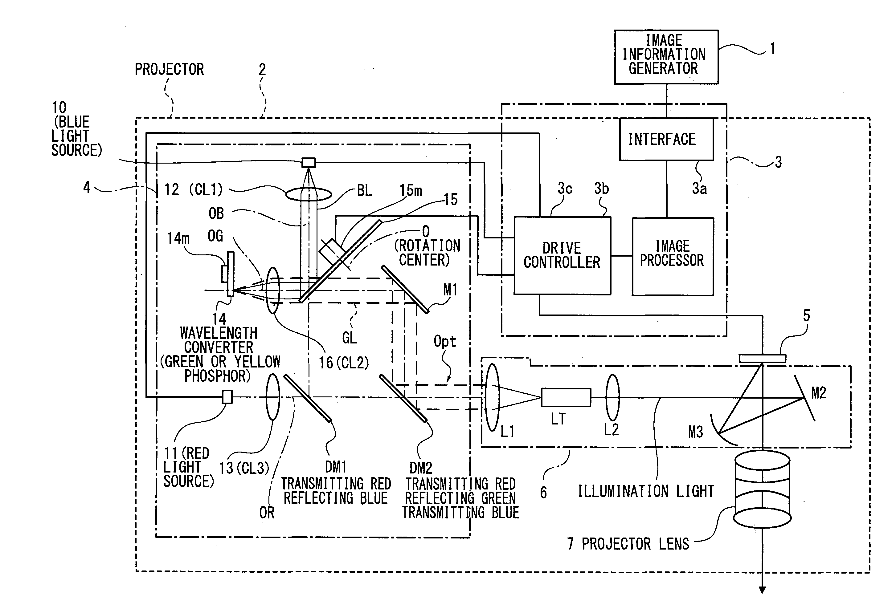
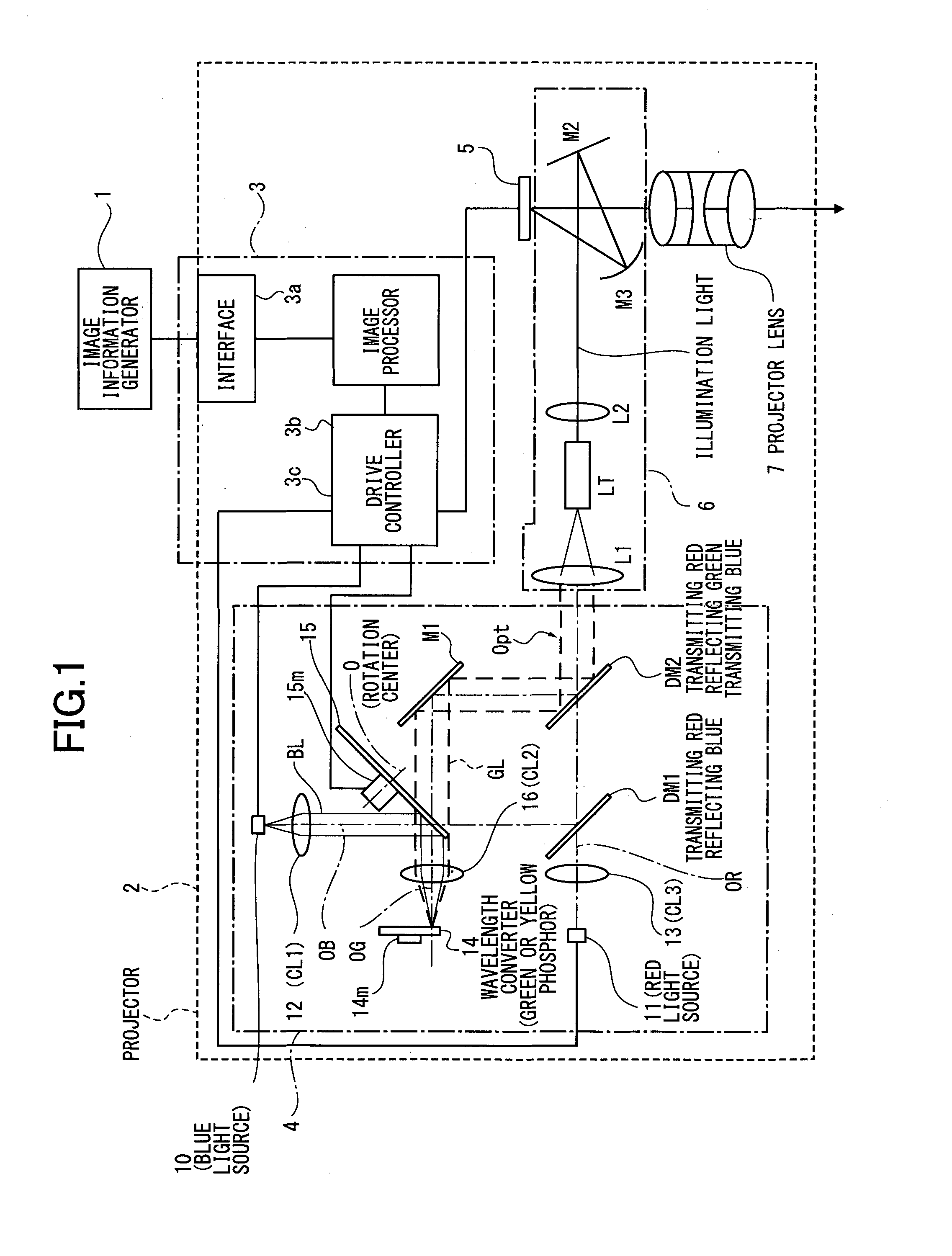
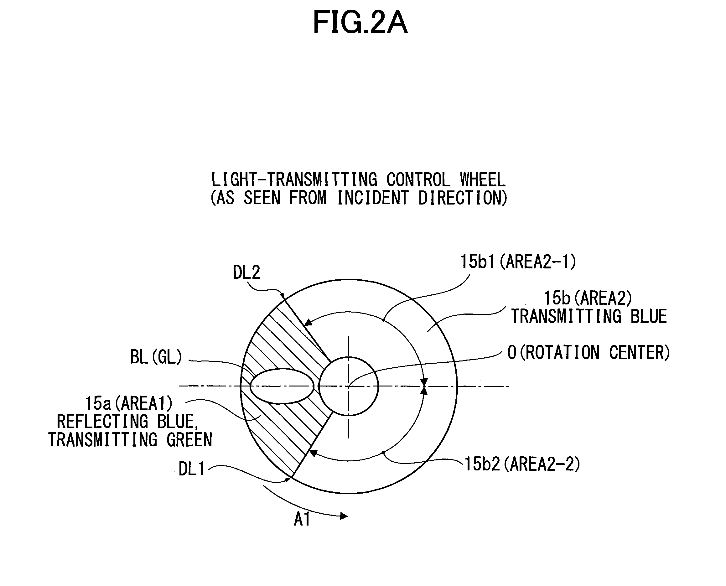
[0029]FIG. 1 is an optical view showing an optical system of a projector incorporating an illumination device according to Embodiment 1 of the present invention. FIG. 2A is a plan view of a light-transmitting control wheel, as viewed from the perpendicular direction to a surface of the light-transmitting control wheel.

[Schematic Construction of Projector]

[0030]In FIG. 1, numeral 1 shows an image information generator of an information processor such as a personal computer. Numeral 2 shows a projector projecting and displaying an enlarged image to a not-shown screen and the like according to image information (image data) generated by the image information generator 1.

[0031]The image information (image data) is generated for a motion picture, a still image, or the like, with color by the image information generator 1, so the image information contains G (green), R (red) and B (blue) image information.

[0032]The projector 2, as shown in FIG. 1, includes a control circuit (c...

modified example of embodiment 1

[0082]In above-described embodiment, the drive controller 3c controls the driving motor 14m so as to rotate the wavelength converter 14 at a constant velocity, such that the incident position of excitation light (blue light) is changed, and the phosphor for use in the wavelength convertor 14 is cooled while not being deteriorated. However, it is not always limited to the above construction.

[0083]For example, the rotation of the wavelength converter 14 can be intermittently controlled. In this regard, the incident position of excitation light can be changed by rotating the wavelength converter 14 so that phosphor used in the wavelength converter 14 can be cooled while not being deteriorated.

[0084]On the other hand, the rotation of the wavelength converter 14 can be controlled under a predetermined condition per certain angle. Namely, when the phosphor used in the wavelength converter 14 is deteriorated on some level, the wavelength converter 14 is rotated at a certain angle, so that ...

embodiment 2

FIGS. 4A and 4B

[0094]The above-described light-transmitting control wheel 15 in Embodiment 1 includes boundary region lines between the first dichroic filter (area 1) 15a and the second dichroic filter (area 2) 15b as shown in FIG. 2A. The boundary region lines are indicated as a first and second boundary parts DL1 and DL2.

[0095]The blue light BL emitted from the solid-state light source 10 has a certain width (refer to FIG. 2A). Thereby, there is a predetermined period while the blue light BL having such a width (hereinafter, referred to as light flux range) crosses the boundary part.

[0096]When the blue light BL in FIG. 1 enters the first and second boundary parts DL1 or DL2 of the light-transmitting control wheel 15, the blue light is incident on both in the first dichroic filter (area 1) 15a and the second dichroic filter (area 2) 15b in FIG. 2A, and the blue light BL emitted from the solid-state light source 10 in FIG. 1 is transmitted through the light-transmitting control whee...


PUM


Abstract

An illumination device includes an excitation light source which emits excitation light, a wavelength converter which generates fluorescent light having a wavelength different from that of the excitation light through the excitation of the excitation light and a light path-splitting member including a first filter and a second filter arranged to alternately come across a light path of the excitation light, wherein the first filter reflects one of the excitation light and the fluorescent light and transmits the other of the excitation light and the fluorescent light, the second filter transmits light reflected by the first filter and reflects light transmitted through the first filter, and the wavelength converter is disposed in a reflection light path or a transmission light path of the excitation light.

Description

TECHNICAL FIELD[0001]The present invention relates to an illumination device having a wavelength converter which emits color light, a projector, and an illumination method.BACKGROUND ART[0002]Recently, display devices having a large-sized screen have become widespread, and are in common use at conferences, presentations, seminars and so on.[0003]There are various displays such as a liquid crystal display or a plasma display. An appropriate one is selected from among the various displays in accordance with the available space or the number of participants when used. In particular, a projector, which is able to project an image to a projection surface such as a screen to be enlarged and displayed thereon, is the most widespread large-screen display because it is relatively reasonable cost-wise and superior in portability (that is, it is small and lightweight).[0004]Recently, greater communication is needed in various situations. In this regard, there are many small meeting rooms or pa...

Claims


Application Information

Patent Timeline
Patent Type & Authority Applications(United States)
IPC IPC(8): G03B21/20G02B26/00G02B13/16F21V9/16F21V9/08
CPCG03B21/204F21V9/16F21V9/08F21Y2101/025G02B26/008F21Y2101/02G02B13/16G02B27/102G02B27/143G03B33/08H04N9/3111H04N9/3158H04N9/3164F21Y2115/10F21Y2115/30G02B27/141
Inventor FUJITA, KAZUHIROTAKAHASHI, TATSUYAMURAI, TOSHIHARUMAEDA, IKUONISHIMORI, TAKEHIRO
Owner RICOH KK
Why Eureka
Try Eureka