Illumination device including a wavelength converter
a wavelength converter and phosphor wheel technology, applied in the direction of projection devices, lighting and heating equipment, instruments, etc., can solve the problem of complicated construction of the phosphor wheel, and achieve the effect of simplifying the phosphor wheel
- Summary
- Abstract
- Description
- Claims
- Application Information
AI Technical Summary
Benefits of technology
Problems solved by technology
Method used
Image
Examples
embodiment 1
Construction
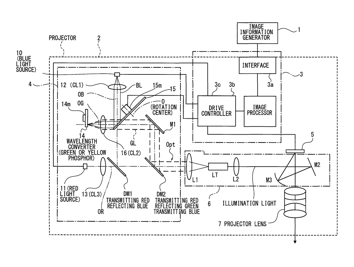
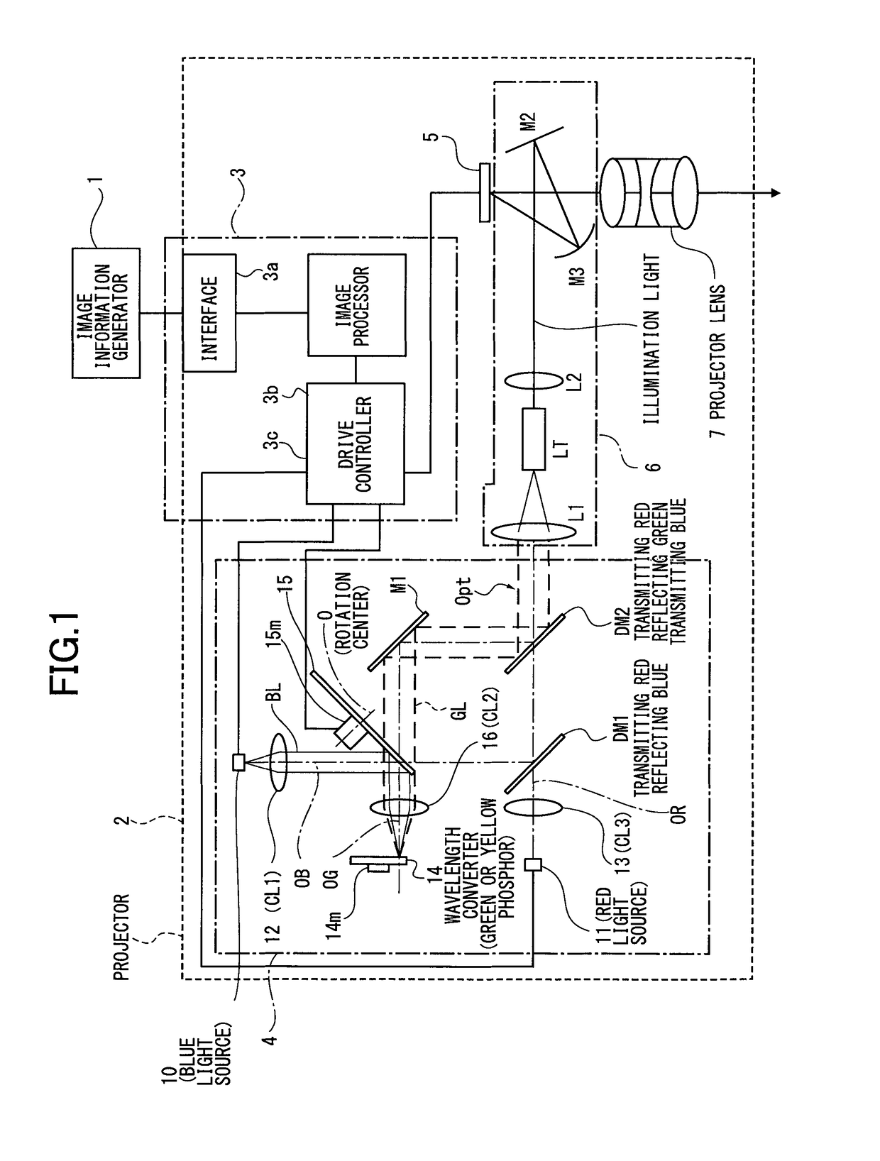
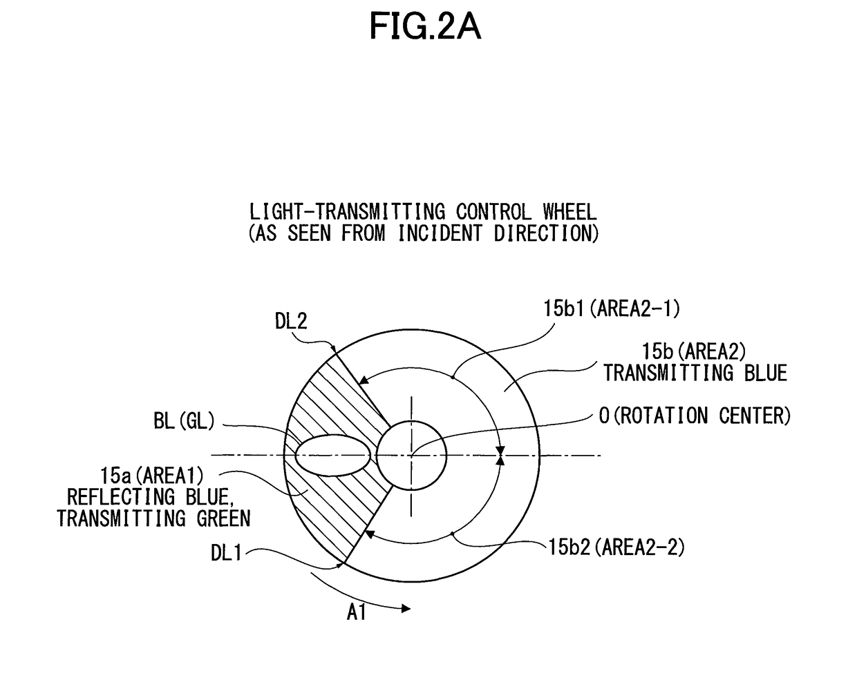
[0029]FIG. 1 is an optical view showing an optical system of a projector incorporating an illumination device according to Embodiment 1 of the present invention. FIG. 2A is a plan view of a light-transmitting control wheel, as viewed from the perpendicular direction to a surface of the light-transmitting control wheel.
[Schematic Construction of Projector]
[0030]In FIG. 1, numeral 1 shows an image information generator of an information processor such as a personal computer. Numeral 2 shows a projector projecting and displaying an enlarged image to a not-shown screen and the like according to image information (image data) generated by the image information generator 1.
[0031]The image information (image data) is generated for a motion picture, a still image, or the like, with color by the image information generator 1, so the image information contains G (green), R (red) and B (blue) image information.
[0032]The projector 2, as shown in FIG. 1, includes a control circuit (c...
modified example of embodiment 1
[0082]In above-described embodiment, the drive controller 3c controls the driving motor 14m so as to rotate the wavelength converter 14 at a constant velocity, such that the incident position of excitation light (blue light) is changed, and the phosphor for use in the wavelength convertor 14 is cooled while not being deteriorated. However, it is not always limited to the above construction.
[0083]For example, the rotation of the wavelength converter 14 can be intermittently controlled. In this regard, the incident position of excitation light can be changed by rotating the wavelength converter 14 so that phosphor used in the wavelength converter 14 can be cooled while not being deteriorated.
[0084]On the other hand, the rotation of the wavelength converter 14 can be controlled under a predetermined condition per certain angle. Namely, when the phosphor used in the wavelength converter 14 is deteriorated on some level, the wavelength converter 14 is rotated at a certain angle, so that ...
embodiment 2
FIGS. 4A and 4B
[0094]The above-described light-transmitting control wheel 15 in Embodiment 1 includes boundary region lines between the first dichroic filter (area 1) 15a and the second dichroic filter (area 2) 15b as shown in FIG. 2A. The boundary region lines are indicated as a first and second boundary parts DL1 and DL2.
[0095]The blue light BL emitted from the solid-state light source 10 has a certain width (refer to FIG. 2A). Thereby, there is a predetermined period while the blue light BL having such a width (hereinafter, referred to as light flux range) crosses the boundary part.
[0096]When the blue light BL in FIG. 1 enters the first and second boundary parts DL1 or DL2 of the light-transmitting control wheel 15, the blue light is incident on both in the first dichroic filter (area 1) 15a and the second dichroic filter (area 2) 15b in FIG. 2A, and the blue light BL emitted from the solid-state light source 10 in FIG. 1 is transmitted through the light-transmitting control whee...
PUM
 Abstract
Description
Claims
Application Information
 - R&D
- Intellectual Property
- Life Sciences
- Materials
- Tech Scout
- Unparalleled Data Quality
- Higher Quality Content
- 60% Fewer Hallucinations
Browse by: Latest US Patents, China's latest patents, Technical Efficacy Thesaurus, Application Domain, Technology Topic, Popular Technical Reports.
© 2025 PatSnap. All rights reserved.Legal|Privacy policy|Modern Slavery Act Transparency Statement|Sitemap|About US| Contact US: help@patsnap.com


