Umbilical buckling testing

a technology of buckling and umbilical tubes, applied in the direction of survey, sealing/packing, borehole/well accessories, etc., can solve the problems of buckling of umbilical tubes, reducing flow rate, cracking, leakage,

Active Publication Date: 2015-09-17
DMAR ENG
View PDF28 Cites 7 Cited by
  • Summary
  • Abstract
  • Description
  • Claims
  • Application Information

AI Technical Summary

Problems solved by technology

As they are being used in deeper and deeper water depth, umbilicals are subject to higher and higher compression loads, which can cause the umbilicals to buckle.
Umbilical buckling has a number of undesirable effects, such as reduction in flow rate, crack, leak, loss of functionality, or failure of the umbilical tubes.

Method used


Image

  • Umbilical buckling testing
  • Umbilical buckling testing
  • Umbilical buckling testing

Examples


Embodiment Construction

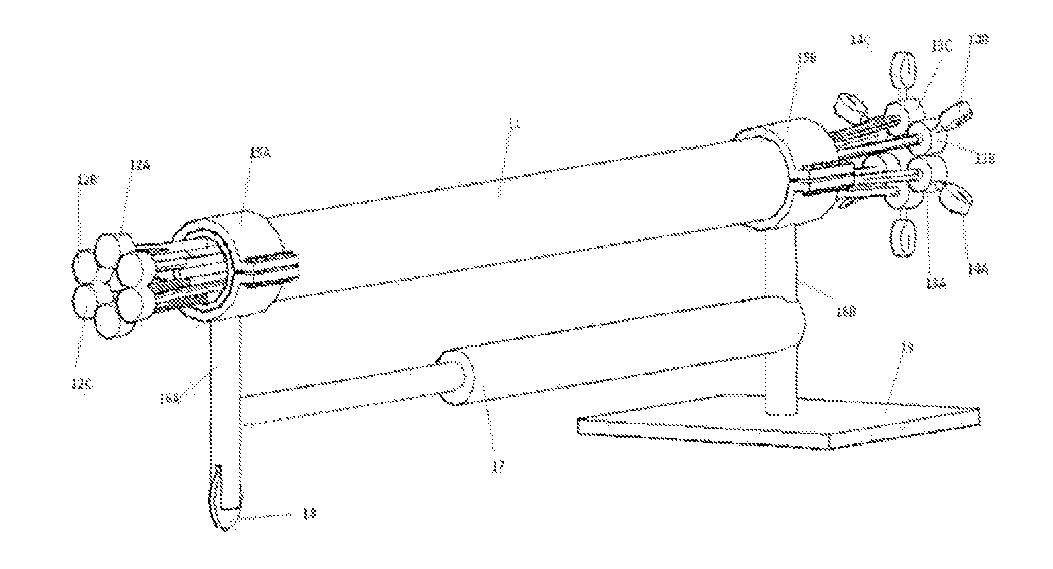
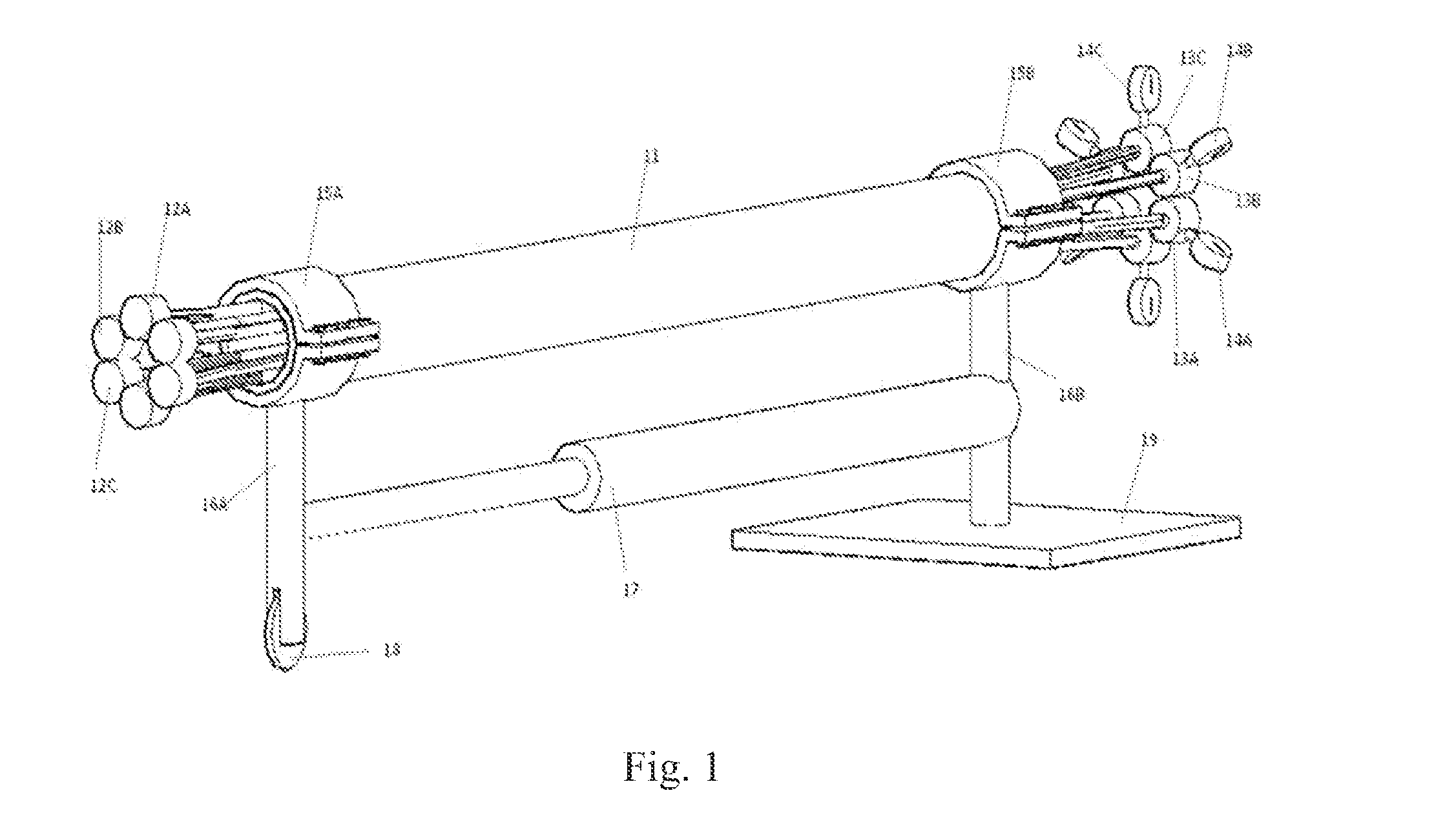
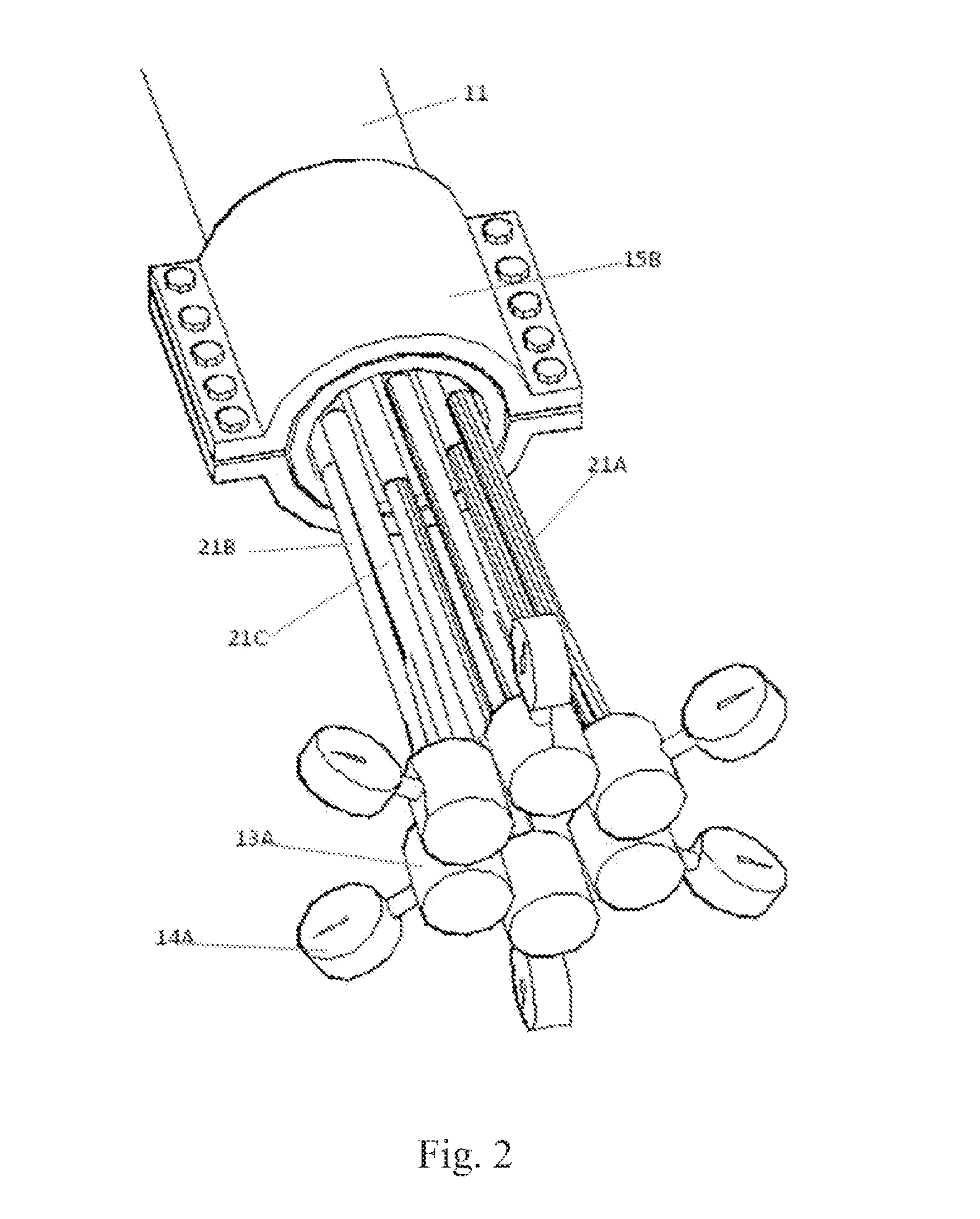
[0007]This document discloses apparatus and methods related to umbilical buckling testing. FIG. 1 shows a diagram of an implementation of the apparatus and methods for umbilical buckling testing. The umbilical buckling testing for an umbilical testing sample 11 can be performed on a testing platform 19, which can be the ground. The umbilical testing sample 11 can be held in place by two fasteners 15A and 15B, each fastening the umbilical testing sample 11 on one end. The fasteners 15A and 15B can be clamps. The fastener 15B can be fixed to the testing platform 19 through a leg 16B, while the fastener 15A is able to slide freely on the ground through a wheel 18 and a leg 16A, which is further attached to an extendable and retractable arm 17. The extendable and retractable arm 17 can be a hydraulic cylinder. The umbilical testing sample 11 can contain a plurality of tubes, and each tube can be connected to two test fittings, one at each end (shown in FIG. 1 as 12A, 12B, and 12C on one...


PUM


Abstract

Apparatus and methods related to umbilical buckling testing are described. For example, some embodiments may contain two damps, a plurality of test fittings, one or more pressure gages, a hydraulic cylinder, and a testing platform, and may be used for testing the umbilical buckling behavior and capacity of an umbilical testing sample.

Description

CROSS REFERENCE TO RELATED APPLICATIONS[0001]This application claims the benefit of U.S. Provisional App. No. 61 / 953,835, Attorney Docket No. DMAR-004-1P, filed on Mar. 15, 2014, which is incorporated herein by reference.FIELD OF PRESENT DISCLOSURE[0002]This present disclosure relates to umbilical buckling testing,BACKGROUND INFORMATION[0003]Umbilicals, such as steel tube umbilicals, are commonly used in oil and gas underwater field developments. Umbilical can consist of many tubes, cables, fibers, and fillers, bundled together. In general, an umbilical is specifically designed for each application, and different field applications tend to have different umbilical cross sections. Therefore, different umbilicals have different buckling behaviors and capacities. As they are being used in deeper and deeper water depth, umbilicals are subject to higher and higher compression loads, which can cause the umbilicals to buckle. Umbilical buckling has a number of undesirable effects, such as ...

Claims


Application Information

Patent Timeline
Patent Type & Authority Applications(United States)
IPC IPC(8): E21B47/00E21B47/01
CPCE21B47/01E21B47/0001E21B17/20E21B41/0007E21B47/007G01N3/08G01N3/20
Inventor HUANG, ZHIMINGZHANG, DAGANG
Owner DMAR ENG
Why Eureka
Try Eureka