Night lighting system, method and component kit

Inactive Publication Date: 2015-09-17
GAMBLE BRUCE
View PDF14 Cites 9 Cited by
  • Summary
  • Abstract
  • Description
  • Claims
  • Application Information

AI Technical Summary

Benefits of technology

The present invention is a motion-activated lighting device that helps people see in dark settings without having to turn on the entire room. It uses a motion sensor to detect a person's movement and a built-in housing to keep the lighting unit active as long as motion is detected. The device includes a light source that escape from the housing and provide a low level of illumination on the floor. This invention aims to promote safety and convenience in dark environments.

Problems solved by technology

This is especially true in commercial establishments, such as hotels, and guest houses, where guests of such establishments may find themselves unfamiliar with their room surroundings and could have trouble maneuvering around the room without lighting, particularly when they attempt to navigate from a bed they are occupying to the bathroom and back again to the bed in the dark unfamiliar environment.
While it is well known to utilize an individual light or sets of lights that are operated by a wall-mounted switch or a switch incorporated into a stand-alone lamp, often the fixed location of the switch or lamp is inconvenient or problematic based on factors like the age or physical condition of the user, and the conditions in the environment of use.
For example, a person, particularly an elderly person, may be disoriented when arising in the dark such that finding a light switch may be difficult.
Likewise, a child may have difficulty finding a light switch at night should he or she need to go to the bathroom, become scared or choose to leave his or her bed for other reasons due to unfamiliarity with the room or poor room design.
Even where sufficient light may be available to locate the switch, a disabled individual may have difficulty physically reaching the switch location.

Method used


Image

  • Night lighting system, method and component kit
  • Night lighting system, method and component kit
  • Night lighting system, method and component kit

Examples


Embodiment Construction

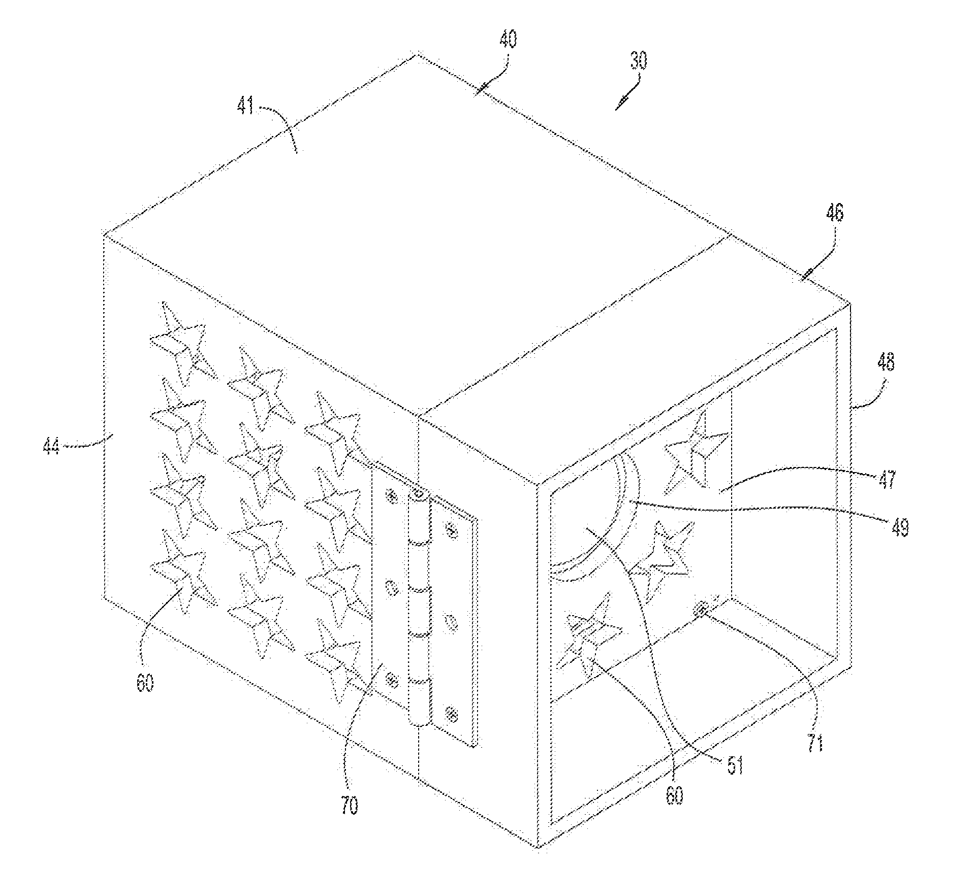
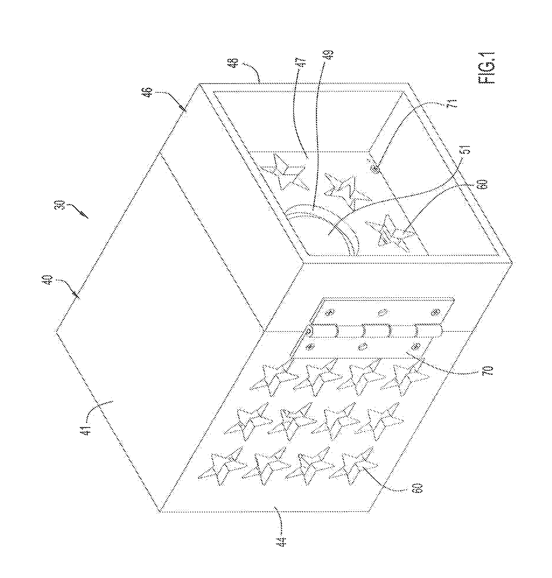
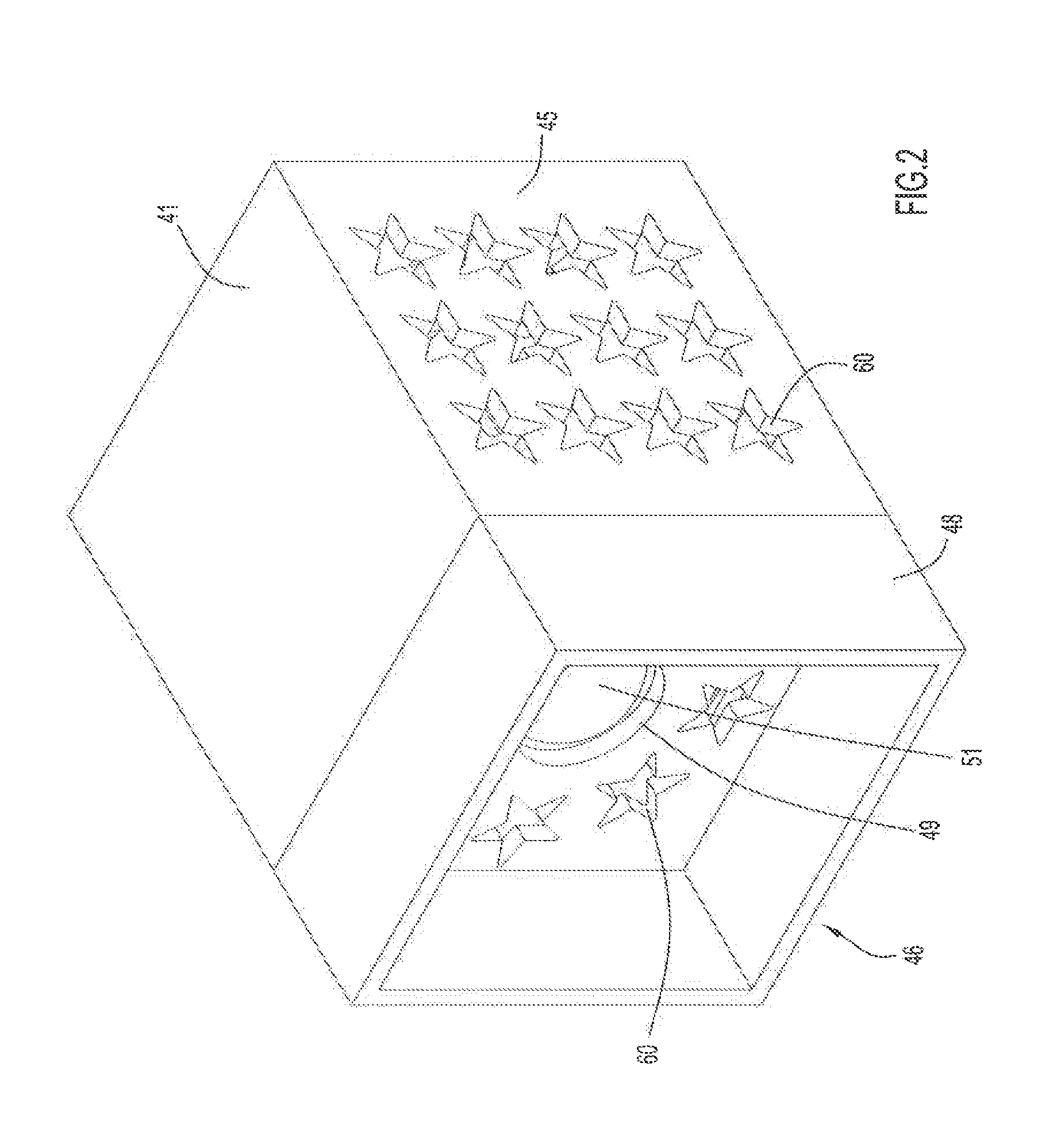
[0034]In accordance with the principles of the invention, in response to detected motion, such as by a person placing his / her foot on or near the floor 10 and suspended adjacent a side of a bed 20, the floor is illuminated by one or more bedside lighting devices 30. The bedside lighting devices 30 are preferably (but not necessarily) battery operated and have a built-in motion sensor such that the field or area of sensed motion 11 encompasses a portion of the floor adjacent the bed 20. The pattern of the field of sensed motion 11 (illustrated via broken lines in FIGS. 16-19) is typically a sector of a circle. Ideally, the motion sensor is positioned such that the field of sensed motion is focused outwardly from the side of the bed. In this way, the motion sensor will not be activated every time someone moves in the bed. Moreover, by having the sensor pointing away from the bed, it will not pick up movement of the covers which occurs as a normal part of the dynamics of a person sleep...


PUM


Abstract

A night lighting device includes a battery powered motion activated lighting unit enclosed within a housing. The housing has walls with light apertures permitting light to escape and provide low level floor illumination. A front panel is pivotally attached to the housing. The front panel has an open peripheral frame and a rear wall set back from an edge of the frame. The open frame extends forwardly from and surrounds the rear wall. The rear wall includes light apertures and a sensor aperture. The open frame focuses the directivity of the motion sensor pattern due to the set back of the rear wall. The top overhang and side extensions of the frame prevent the motion sensing field from dispersing upwardly and laterally. Additionally, a kit is provided which includes the motion activated lighting device, a separate motion sensing lighting unit, and other components.

Description

CROSS REFERENCE TO RELATED APPLICATIONS[0001]The present application is a non-provisional application based on and claiming priority from U.S. Provisional Application No. 61 / 952,360, entitled “Night Lighting System, Method and Component Kit”, filed Mar. 13, 2014, the disclosure which is hereby incorporated herein by reference in its entirety.FIELD OF THE INVENTION[0002]The present invention pertains generally to night lighting systems and methods, and to a night lighting kit containing components to effect the systems and methods of the invention. More particularly, the invention is primarily concerned with providing motion activated supplemental lighting for use by persons in dark environments, particularly unfamiliar environments such as a room in a hotel, inn, or guest house, to facilitate ease in traversing a path from a bed to the bathroom and from the bathroom back to the bed. The invention may also be used in one's own home environment.BACKGROUND OF THE INVENTION[0003]Individ...

Claims


Application Information

Patent Timeline
IPC IPC(8): F21V23/04F21V17/10F21V7/00F21S8/00F21V11/14
CPCF21V23/0471F21S8/035F21W2121/00F21V7/0091F21V17/105F21V11/14F21S9/022F21V15/01F21V17/007F21V21/096F21V23/0464F21Y2115/10
Inventor GAMBLE, BRUCE
Owner GAMBLE BRUCE
Why Eureka
Try Eureka