Eureka AIR delivers breakthrough ideas for toughest innovation challenges, trusted by R&D personnel around the world.

Standby Instrument Panel For Aircraft

a technology for aircraft and instruments, applied in the direction of instruments, navigation instruments, static indicating devices, etc., can solve the problem of transition to a single electronic display accessible by all members, and achieve the effect of limiting the scope of invention

Active Publication Date: 2015-09-17
TEXTRON INNOVATIONS
View PDF6 Cites 22 Cited by
  • Summary
  • Abstract
  • Description
  • Claims
  • Application Information

AI Technical Summary

Benefits of technology

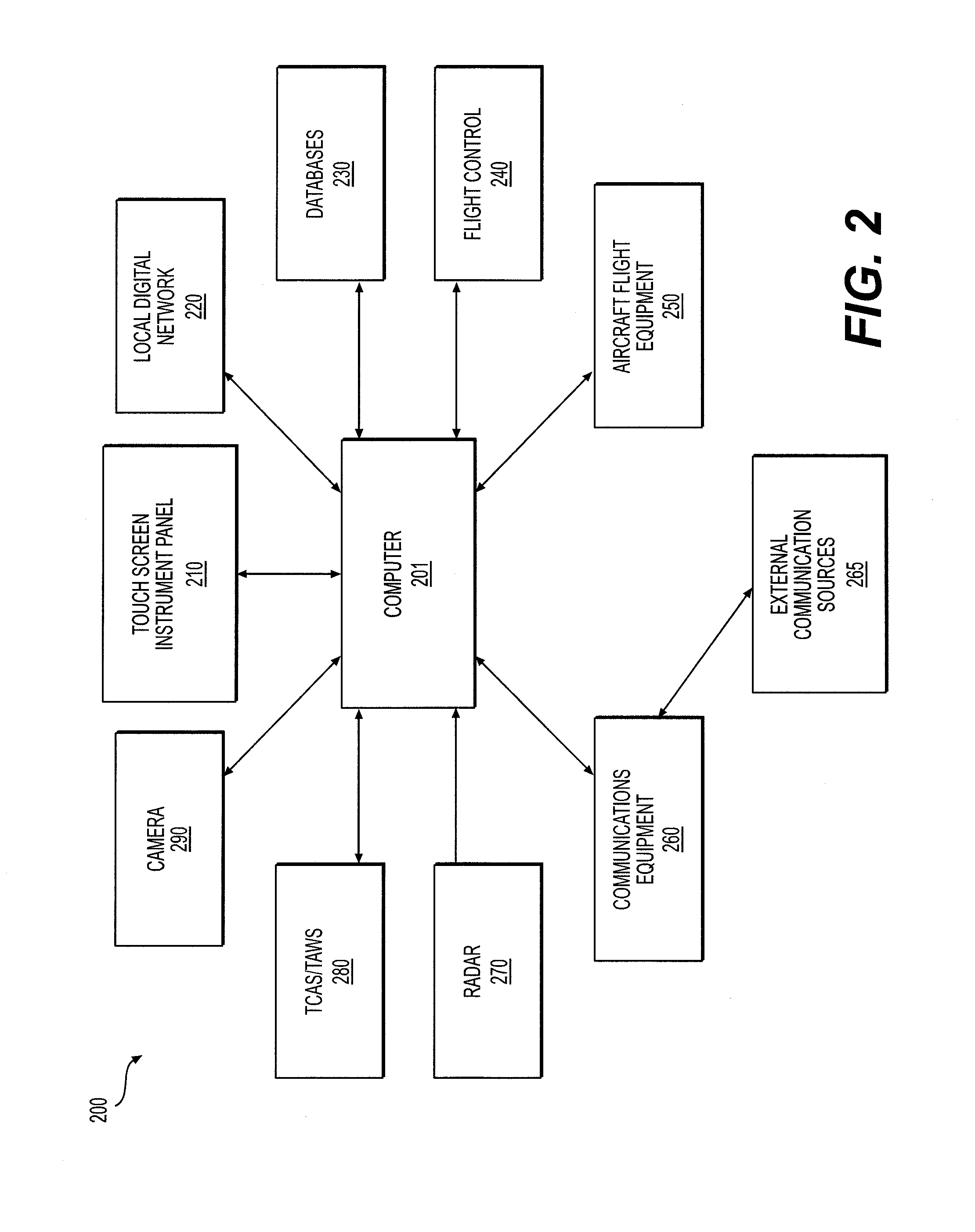
The invention is a vehicle instrument panel system that includes a touch-screen display and a standby instrument that can be partially or fully hidden from view. When power is lost, the standby instrument becomes viewable through the display. The system can be used in an aircraft cockpit and includes a backup device located behind the display panel for use in case of power loss. The display panel can be a touch screen that interfaces with multiple aircraft systems and can take the place of controls used for interaction. The technical effect of the invention is to provide a more efficient and effective way of displaying and accessing vehicle systems, particularly in situations where power is lost or there is a need for a standby instrument.

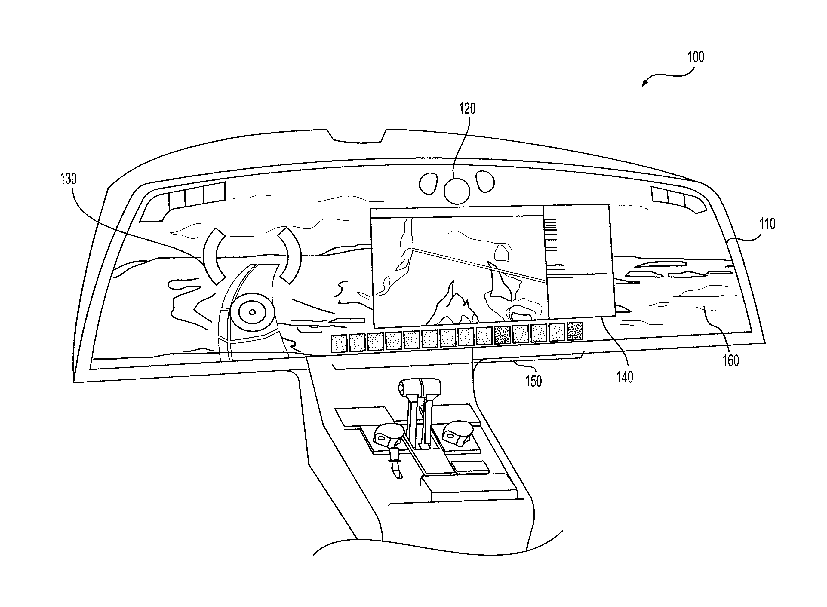
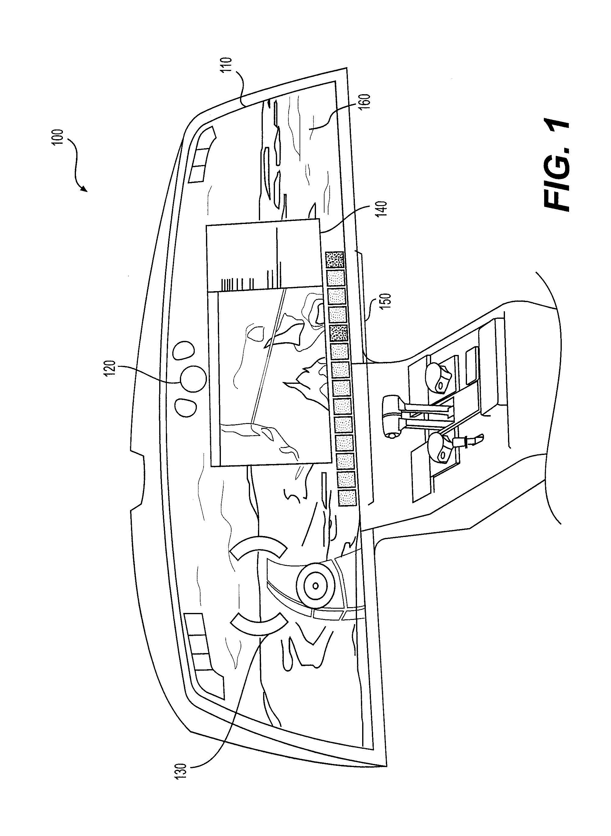
Problems solved by technology

However, access to the standby instruments must always be available, which has heretofore prevented a transition to a single electronic display accessible by all members of the flight crew.

Method used


Image

  • Standby Instrument Panel For Aircraft
  • Standby Instrument Panel For Aircraft
  • Standby Instrument Panel For Aircraft

Examples


Embodiment Construction

[0013]Systems for providing backup instrument readings in conjunction with the display of real-time images in the cockpit of an aircraft are described herein. In embodiments, the system 100 includes a secondary instrument panel 320 provided behind a touch-screen instrument panel (TSIP) 130 located in the cockpit of an aircraft.

[0014]FIG. 1 illustrates an embodiment of a TSIP. The TSIP replaces the plurality of instruments typically located in an aircraft cockpit, including dials, gauges, and screens that would traditionally be located on the console of an aircraft. The TSIP is configured for at least a touch screen implementation. In some embodiments, the TSIP may span the width of a cockpit of an aircraft. As illustrated in FIG. 1, the TSIP is the width of the cockpit and may be accessed simultaneously by anyone present in the cockpit (e.g., the pilot and co-pilot).

[0015]The TSIP is a digital information panel that may include a plurality of digital layers. The digital layers may o...


PUM


Abstract

A system and method for displaying standby instrument information is disclosed. The touch-screen instrument panel system for a vehicle has a touch-screen information panel display configured to display vehicle operation information received from a computing system and a standby instrument display that is secured to an area located behind the information panel display. The standby instrument display is hidden from view when the information panel display is in a powered state but is in full view when the information panel display is in an unpowered state.

Description

CROSS-REFERENCE TO RELATED APPLICATIONS[0001]This application claims the benefit of U.S. Provisional Application No. 61 / 951,145, entitled “3D Weather”, U.S. Provisional Application No. 61 / 951,189, entitled “HD Camera”, U.S. Provisional Application No. 61 / 951,260, entitled “Adjustable Synthetic Vision System”, U.S. Provisional Application No. 61 / 951,231, entitled “Skytrak Navigational Aid”, U.S. Provisional Application No. 61 / 951,240, entitled “Smart Airport Application”, U.S. Provisional Application No. 61 / 951,243, entitled “Smart Traffic Application”, U.S. Provisional Application No. 61 / 951,157, entitled “Chart Synoptic Window”, U.S. Provisional Application No. 61 / 951,168 entitled “Flight Planning Synoptic Window”, U.S. Provisional Application No. 61 / 951,201 entitled “Intelligent Radio Frequency Identifiers”, U.S. Provisional Application No. 61 / 951,152, entitled “Crew Alerting System”, U.S. Provisional Application No. 61 / 951,195 entitled “Historical Data Feature”, U.S. Provisional ...

Claims


Application Information

Patent Timeline
Patent Type & Authority Applications(United States)
IPC IPC(8): G09G5/00
CPCG09G5/003B64D43/00G01C23/00G06F3/0488G06F2203/04804G09G5/14G09G2340/10G09G2340/12G09G2380/12
Inventor KNEUPER, JEREMY JOSEPHSTANFIELD, ISAAC WAYNEDECKER, JASON MICHAELLANIER, JOHN ROBERTPINKERTON, CHRISTOPHER ADAIR
Owner TEXTRON INNOVATIONS
Why Eureka
Eureka Blog
Learn More