

Cover for switch to which a frame is attachable and an operation terminal
a technology of operation terminal and frame, which is applied in the direction of emergency connections, emergency contacts, emergency actuators, etc., can solve the problems of deteriorating operation feeling when the switch is pressed, the push-button handle is not easily moved in a straight direction, etc., and achieves the effect of improving the operation feeling of the push-button handl
- Summary
- Abstract
- Description
- Claims
- Application Information
AI Technical Summary
Benefits of technology
Problems solved by technology
Method used
Image

Examples
first exemplary embodiment
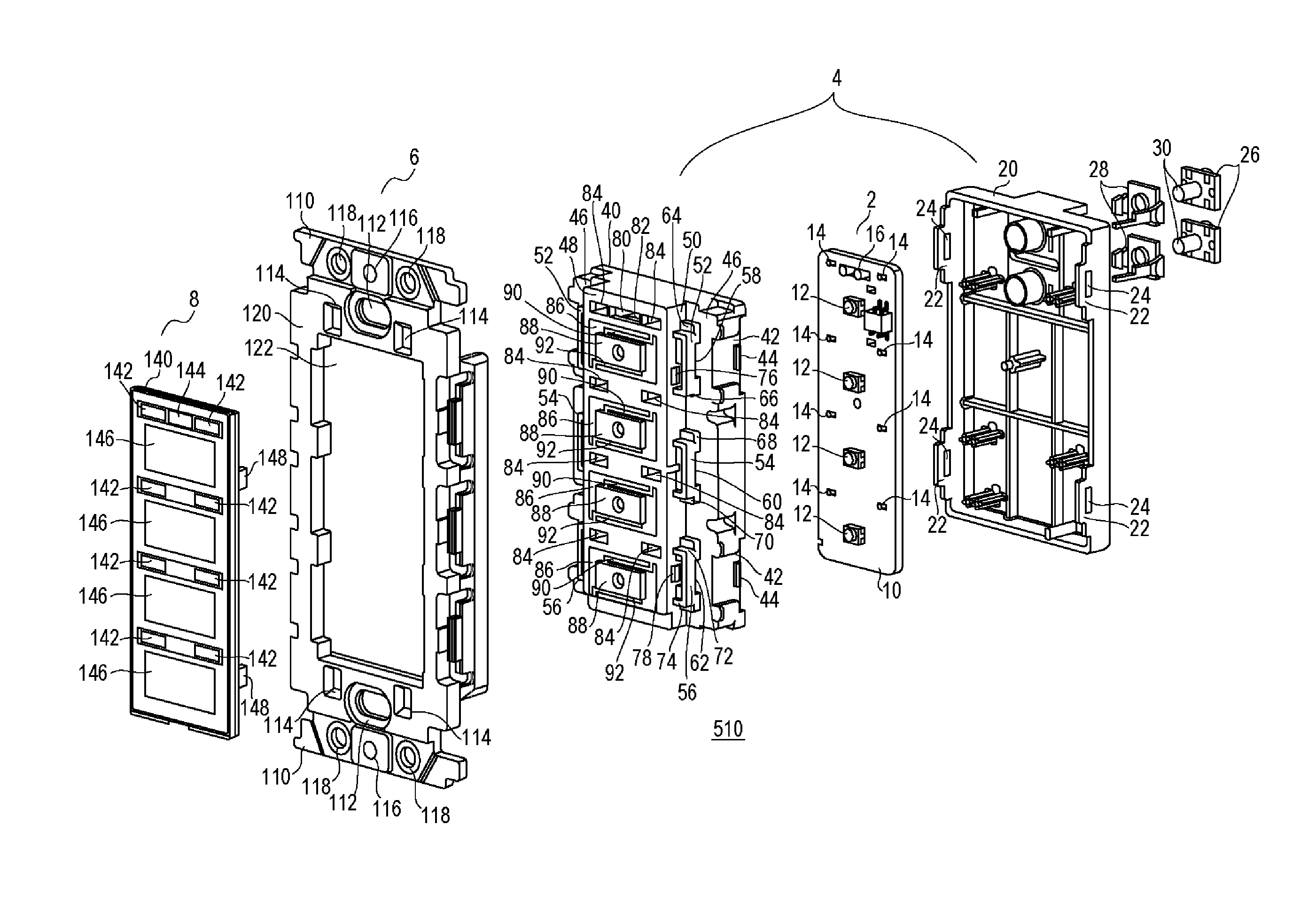
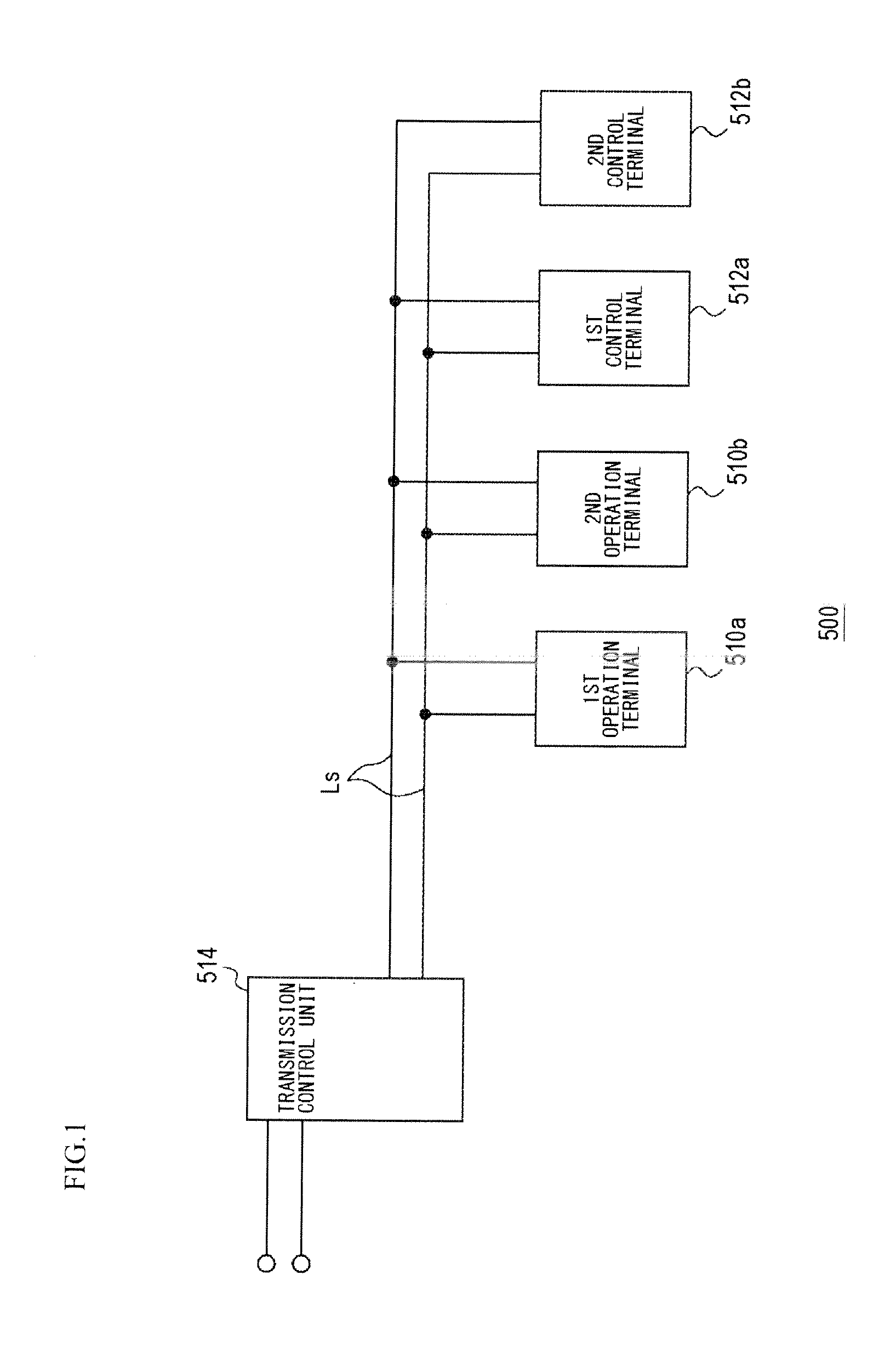
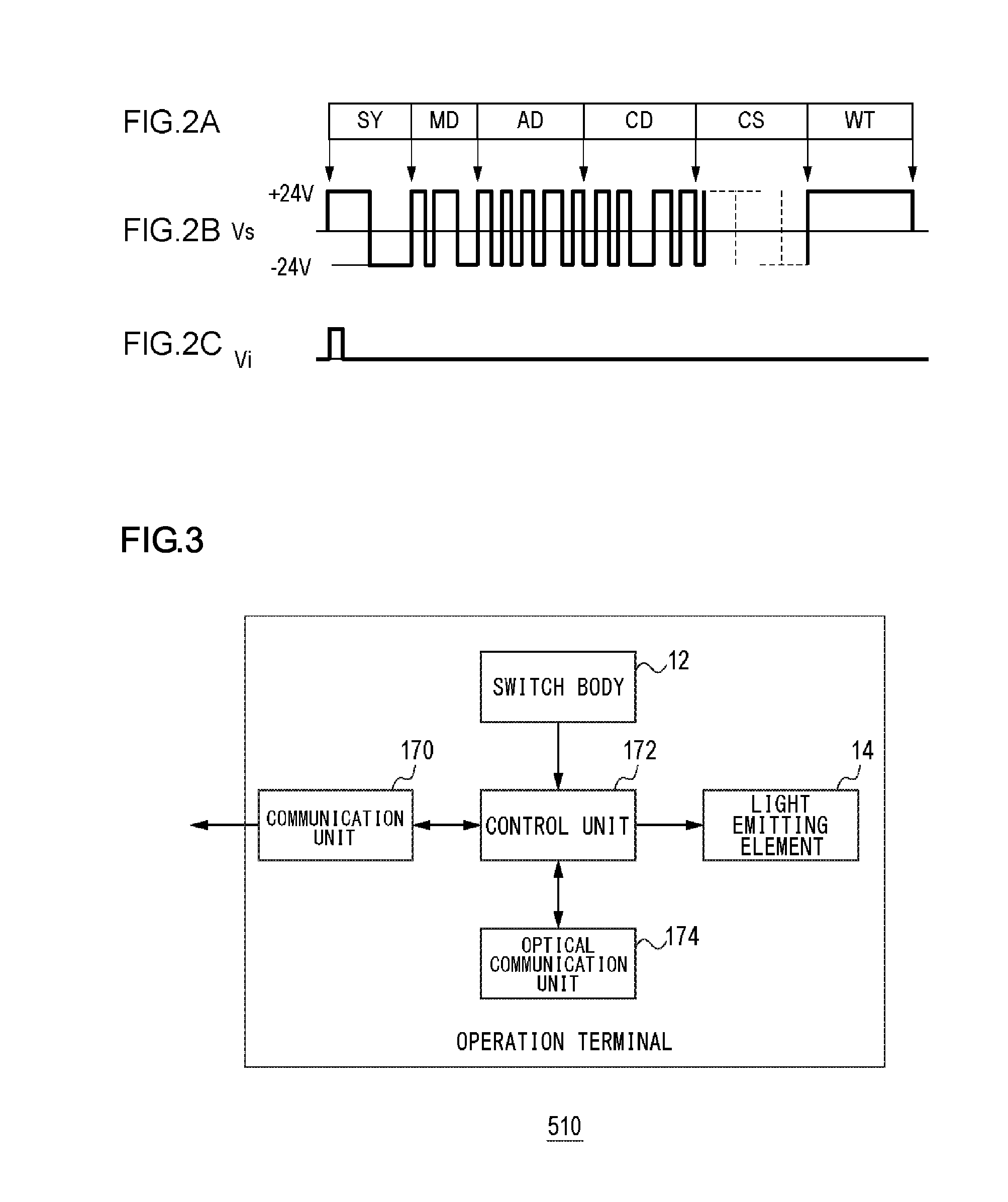
[0035]The inventor's knowledge underlying the disclosure will be explained before a first exemplary embodiment of the disclosure is explained. The first exemplary embodiment of the disclosure relates to a cover for switch or switches of an operation terminal included in a remote monitoring control system. Here, the “cover for switch” may instead be referred to as or expressed by a “cover for a switch”, a “cover for switches”, a “switch cover”, a “switch's cover”, “switches' cover” or else, where appropriate. If a cover and a push-button handle are constituted as separate components, a production process of engaging the push-button handle with the cover will be carried out when an operation terminal is to be assembled. This process is counted as loss in terms of the assembly time and cost. In order to cope with this, it is advisable that the cover and the push-button handle are formed integrally with each other with an arm or arms placed therebtween. If, however, the cover and the pu...
second exemplary embodiment
[0083]Similar to the first exemplary embodiment, the second exemplary embodiment relates to a cover for switches of an operation terminal included in a remote monitoring control system. The second exemplary embodiment differs from the first exemplary embodiment in that the shape of the two arms differ. A description is given here centering around the difference from the first exemplary embodiment.
[0084]FIG. 15 is a perspective view of a cover 40, for switch, according to the second exemplary embodiment of the disclosure. FIG. 15 is illustrated in such a manner as to be comparable to FIG. 4 and FIG. 10 in the first exemplary embodiment. The components of FIG. 15, where the same reference numerals are given as those of FIG. 4 and FIG. 10, have the same shapes and functions corresponding to those of FIG. 4 and FIG. 10. Of the components shown in FIG. 15, the reference numerals may not be assigned at all if such components thereof are identical to those shown in FIG. 4 and FIG. 10. An o...
third exemplary embodiment
[0090]Similar to the first and second exemplary embodiments, the third exemplary embodiment relates to a cover for switches of an operation terminal included in a remote monitoring control system. The cover for switches according to the first and second exemplary embodiments has two arms. On the other hand, the cover for switches according to the third exemplary embodiments has a single arm. As described in the first and second exemplary embodiments, the operability is improved by using the two arms. The third exemplary embodiment, however, achieves a structure still keeping the excellent operability even with a single arm used. A description is first given hereunder of a case where the operability is generally degraded when a single arm. Then, a description is given of the cover, for switches, according to the third exemplary embodiment centering around the differences from the first and second exemplary embodiments.
[0091]FIG. 17 is a perspective view of a cover 300 for switches, w...
PUM
 Abstract
Description
Claims
Application Information