Sensor Faucet

a technology of sensor and faucet, applied in the field of faucet, can solve problems such as water was

Inactive Publication Date: 2015-09-24
LIN MING SHUAN
View PDF2 Cites 6 Cited by
  • Summary
  • Abstract
  • Description
  • Claims
  • Application Information

AI Technical Summary

Benefits of technology

[0008]According to this invention, a sensor faucet comprises a housing, a water output unit, a water input unit, an electromagnetic valve, first and second sensors and a controller. The water output unit is disposed in the housing. The water input unit is disposed in the housing. The electromagnetic valve is disposed in the housing, and is coupled between the water output unit and the water input unit for permitting fluid communication between the water output unit and the water input unit when activated, and for preventing fluid communication between the water output unit and the water input unit when deactivated. The first sensor is mounted to the housing, is capable of sensing an object in proximity thereto, and generates a first sensing signal. The second sensor is mounted to the housing, is capable of sensing an object in proximity thereto, and generates a second sensing signal. The controller is disposed in the housing, is coupled to the first and second sensors and the electromagnetic valve, and receives the first and second sensing signals respectively from the first and second sensors. The controller controls, based on the first sensing signal, an indication of a state indicator between an inactive state and an active state, and generates a control signal based on the indication of the state indicator and the first and second sensing signals to control activation and deactivation of the electromagnetic valve.

Problems solved by technology

Even if outflow of water is not desired, water flows out of the conventional sensor faucet if, for instance, an insect happens to be in proximity to the sensor, or if a kitchenware or even the user is accidentally or unintentionally in proximity to the sensor, thereby resulting in waste of water.

Method used


Image

  • Sensor Faucet
  • Sensor Faucet
  • Sensor Faucet

Examples


Embodiment Construction

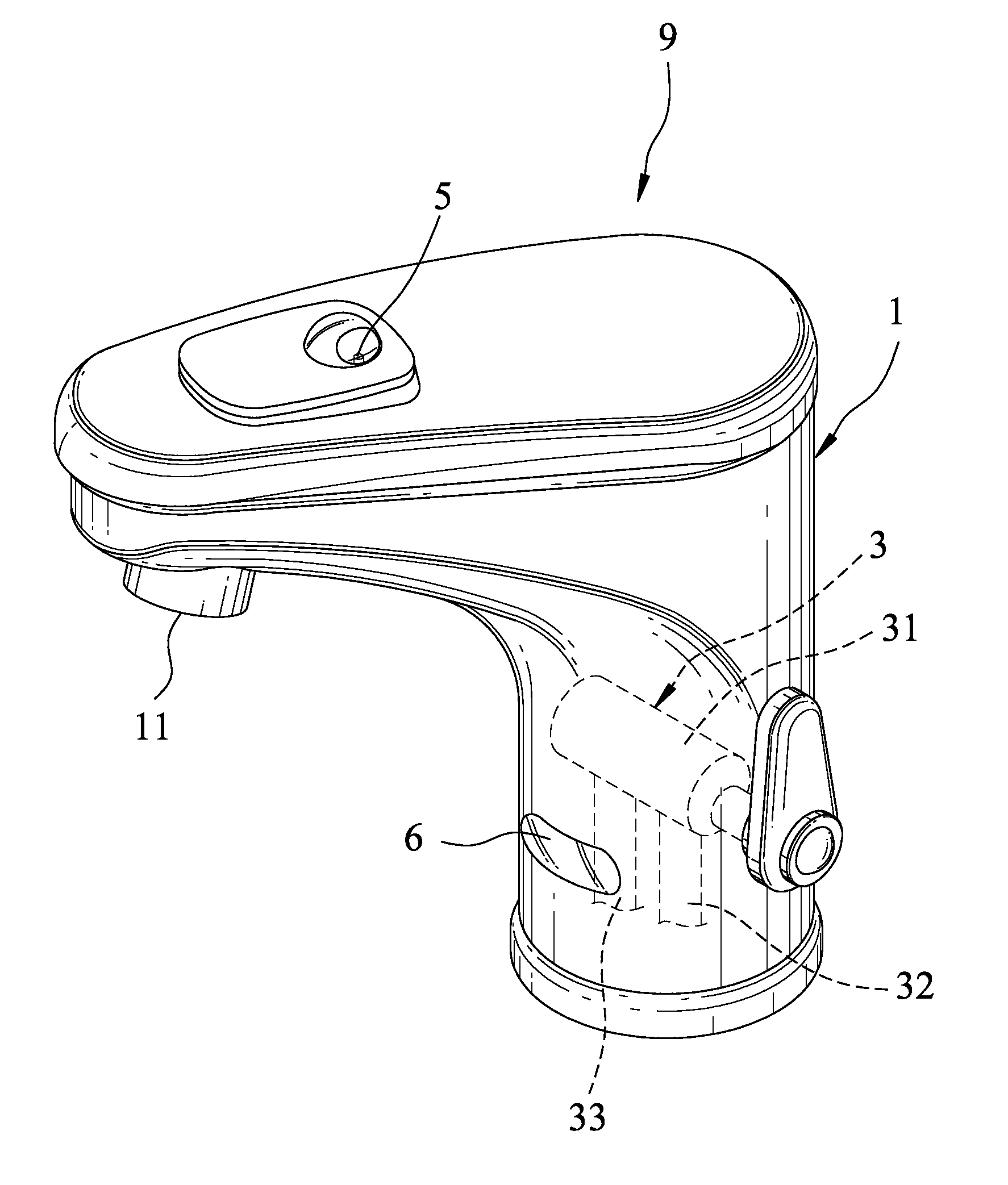
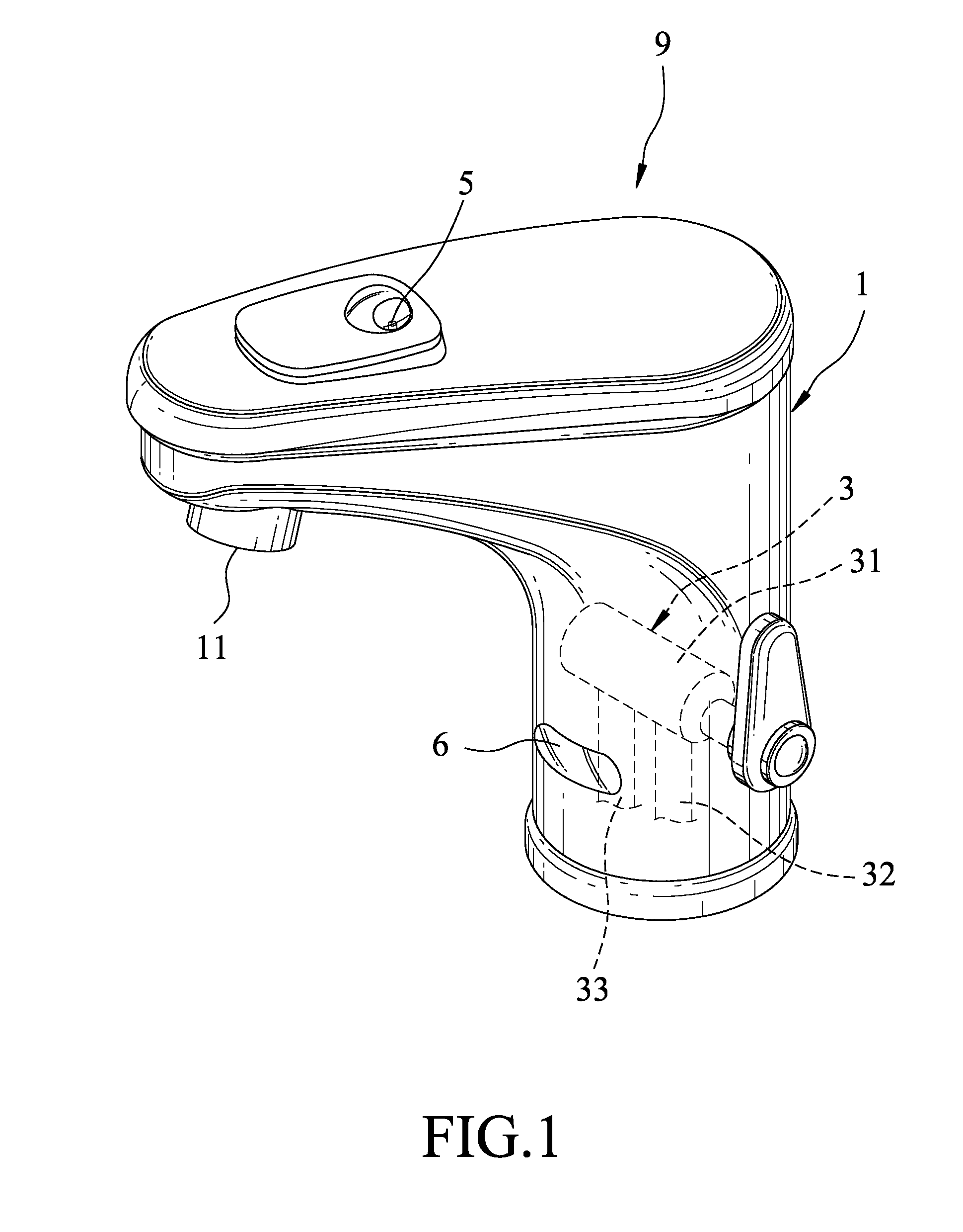
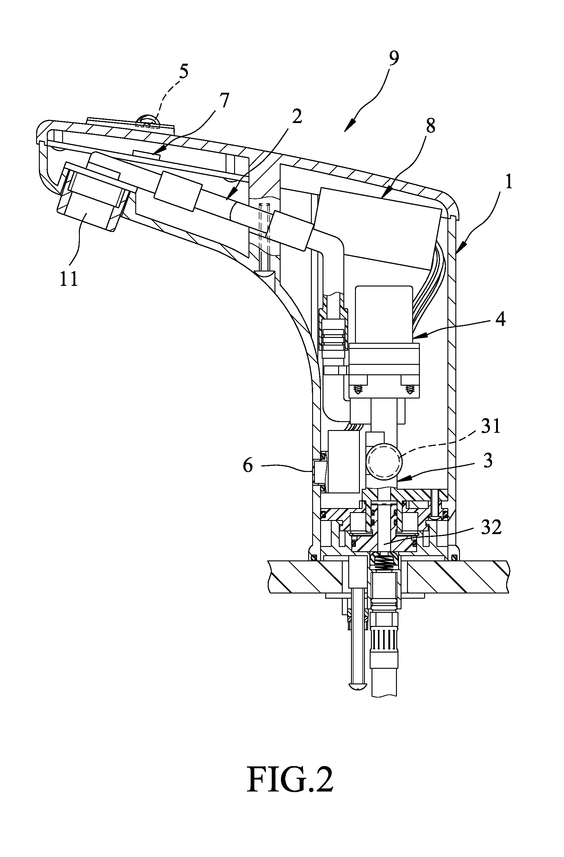
[0014]Referring to FIGS. 1 to 3, the preferred embodiment of a sensor faucet according to this invention includes a housing 1, a water output unit 2, a water input unit 3, an electromagnetic valve 4, first and second sensors 5, 6, a controller 7 and a battery 8.

[0015]The housing 1 has a spout 11.

[0016]The water output unit 2 is disposed in the housing 1, and has a first end coupled to the spout 11, and a second end.

[0017]The water input unit 3 is disposed in the housing 1. In this embodiment, the water input unit 3 includes a mixing valve 31, a cold water input conduit 32 which is coupled to the mixing valve 31 and into which cold water flows, and a hot water input conduit 33 which is coupled to the mixing valve 31 and into which hot water flows. The mixing valve 31 mixes the cold water from the cold water input conduit 32 and the hot water from the hot water input conduit 33, and outputs mixed water. In other embodiments, the water input unit 3 may only include the cold water input...


PUM


Abstract

A sensor faucet includes: a housing; a water output unit, a water input unit, an electromagnetic valve and a controller disposed in the housing; and first and second sensors mounted to the housing. The electromagnetic valve is coupled between the water input and output units for controlling fluid communication therebetween. Each of the first and second sensors senses an object in proximity thereto, and generates a respective one of first and second sensing signals. The controller controls, based on the first sensing signal, an indication of a state indicator between active and inactive states, and controls, based on the state indicator and the first and second sensing signals, activation and deactivation of the electromagnetic valve.

Description

CROSS-REFERENCE TO RELATED APPLICATION[0001]This application claims priority of Taiwanese Application No. 103204892, filed on Mar. 21, 2014, the contents of which are hereby incorporated by reference.BACKGROUND OF THE INVENTION[0002]1. Field of the Invention[0003]This invention relates to a faucet, and more particularly to a sensor faucet.[0004]2. Description of the Related Art[0005]A conventional sensor faucet includes a sensor and an electromagnetic valve. The sensor uses infrared sensing techniques to sense an object (e.g., a hand of a user) in proximity thereto. Upon sensing an object in proximity thereto, the sensor activates the electromagnetic valve so as to allow outflow of water from the conventional sensor faucet. Otherwise, i.e., when there is no object in proximity to the sensor, the sensor deactivates the electromagnetic valve so as to prevent outflow of water from the conventional sensor faucet.[0006]Even if outflow of water is not desired, water flows out of the conve...

Claims


Application Information

Patent Timeline
Patent Type & Authority Applications(United States)
IPC IPC(8): E03C1/05
CPCE03C1/057
Inventor LIN, MING-SHUAN
Owner LIN MING SHUAN
Why Eureka
Try Eureka