Electrical connector assembly

a technology of electrical connectors and connector parts, applied in the direction of fixed connections, coupling device connections, coupling protective earth/shielding arrangements, etc., can solve the problems of insufficient transmission rate of usb 2.0, cracks in electrical plug connectors, and disassembly of elastic transmission terminals or tongues, so as to improve crosstalk interference between plate terminals and improve the structural strength of tongues, the effect of improving the crosstalk interference between elastic terminals

Active Publication Date: 2015-09-24
ADVANCED CONNECTEK INC
View PDF25 Cites 51 Cited by
  • Summary
  • Abstract
  • Description
  • Claims
  • Application Information

AI Technical Summary

Benefits of technology

[0011]In conclusion, since the upper-row plate terminals and the lower-row plate terminals are arranged upside down, and the pin configuration of the upper-row plate signal terminals is left-right reversal with respect to that of the lower-row plate signal terminals. Accordingly, when the electrical plug connector is inserted into the electrical receptacle connector by a first orientation where the upper plane of the electrical plug connector is facing up, the upper-row elastic terminals of the electrical plug connector are in contact with the upper-row plate signal terminals of the electrical receptacle connector. Conversely, when the electrical plug connector is inserted into the electrical receptacle connector by a second orientation where the lower plane of the electrical plug connector is facing up, the upper-row elastic terminals of the electrical plug connector are in contact with the lower-row plate signal terminals of the electrical receptacle connector. Consequently, the inserting orientation of the electrical plug connector is not limited when inserting into the electrical receptacle connector. Moreover, a plurality of hook structures is protruded at the two sides of the tongue portion. Therefore, when the electrical plug connector is inserted into the electrical receptacle connector, the elastic pins at two sides of the electrical plug connector would not wear against the two sides of the tongue portion. In addition, a first grounding sheet is configured to the first insulation housing and between the upper-row plate contact segment and the lower-row plate contact segment, thus the crosstalk interference between the plate terminals can be improved by the first grounding sheet during signal transmission. Furthermore, the structural strength of the tongue portion can be further enhanced.
[0012]Additionally, since the upper-row elastic terminals and the lower-row elastic terminals are arranged upside down, and the pin configuration of the upper-row elastic signal terminals is left-right reversal with respect to that of the lower-row elastic signal terminals. When the electrical plug connector is inserted into an electrical receptacle connector by a first orientation where an upper plane of the electrical plug connector is facing up, the upper-row elastic terminals of the electrical plug connector are in contact with upper-row plate signal terminals of the electrical receptacle connector. Conversely, when the electrical plug connector is inserted into the electrical receptacle connector by a second orientation where the upper plane of the electrical plug connector is facing down, the upper-row elastic terminals of the electrical plug connector are in contact with lower-row plate signal terminals of the electrical receptacle connector. Consequently, the inserting orientation of the electrical plug connector is not limited when inserting into an electrical receptacle connector. Besides, a plurality of clamping structures are extending and inserted into two sides of the mating room to be in contact with buckle elastic sheets located at two sides of an electrical receptacle connector. Therefore, the clamping structures are connected to the metal shell for conduction and grounding. Furthermore, a grounding sheet is located on the insulation housing and between the upper-row elastic terminals and the lower-row elastic terminals, thus the crosstalk interference between the elastic terminals can be improved by the second grounding sheet during signal transmission.

Problems solved by technology

The transmission rate of USB 2.0 is insufficient.
When the conventional USB electrical receptacle connector with the conventional USB electrical plug connector in an improper orientation, the elastic transmission terminals or a tongue portion of the conventional USB electrical plug connector may be damaged or even broken, resulting in the disablement of the elastic transmission terminals or the tongue portion.
Furthermore, the surface of an iron shell of the conventional USB electrical receptacle connector or the surface of the conventional USB electrical plug connector is provided with a crack for firmly connection.
However, these cracks would adversely influence the shielding effect of the iron shell to induce interferences (such as Electromagnetic Interference (EMI), Radio-Frequency Interference (RFI), and the like), with other signals during signal transmission.
Therefore, a problem of serious crosstalk between the terminals of conventional connector is to be solved.

Method used


Image

  • Electrical connector assembly
  • Electrical connector assembly
  • Electrical connector assembly

Examples


Embodiment Construction

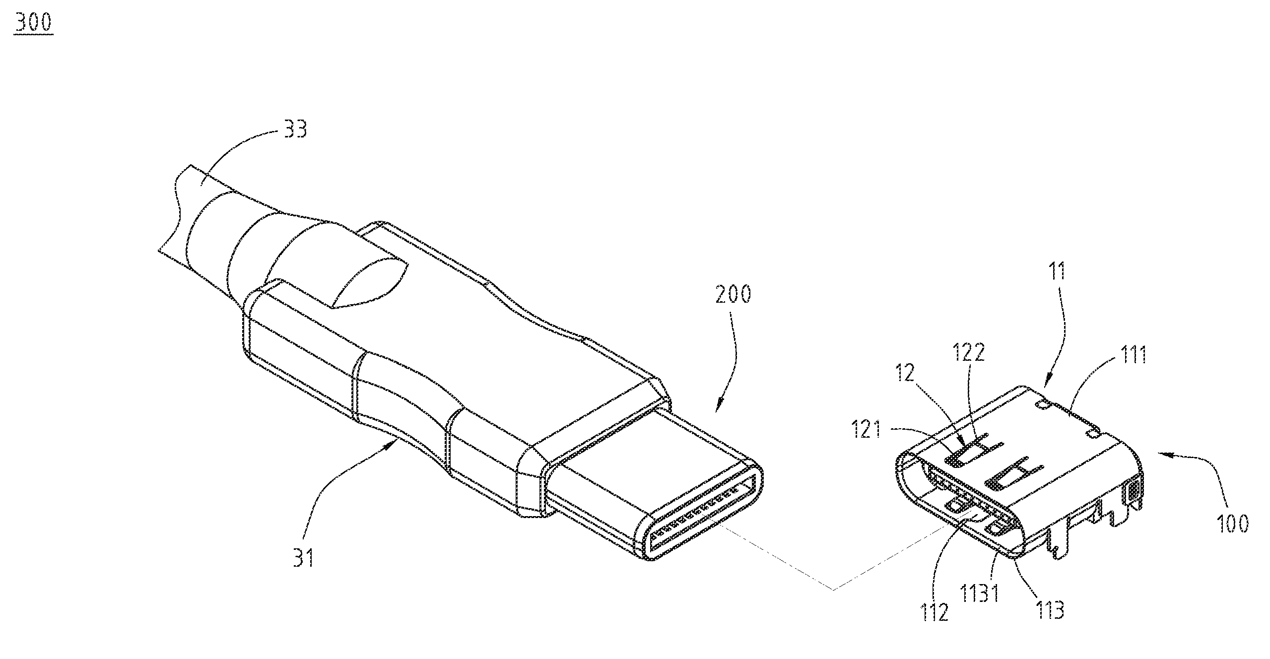
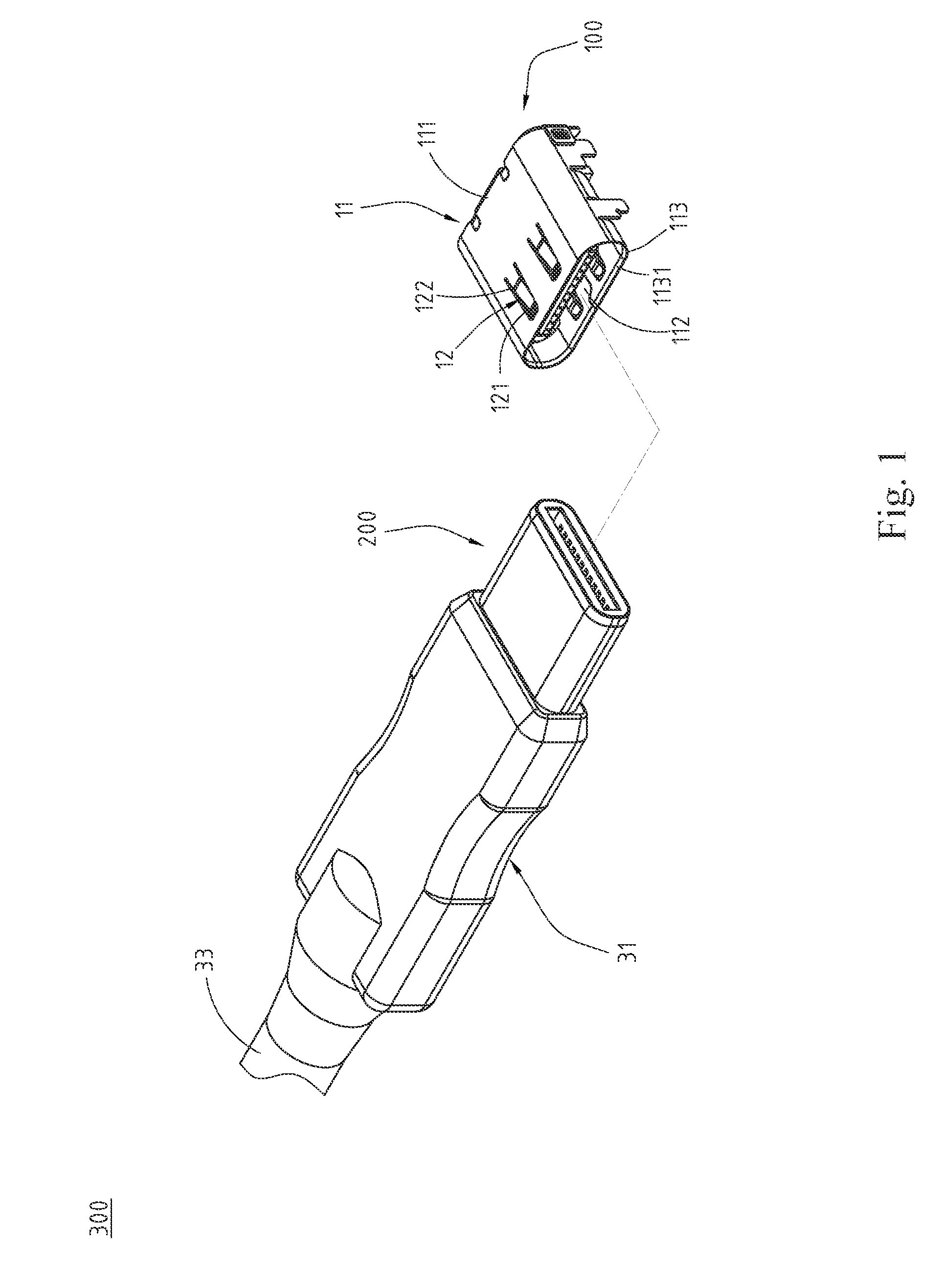
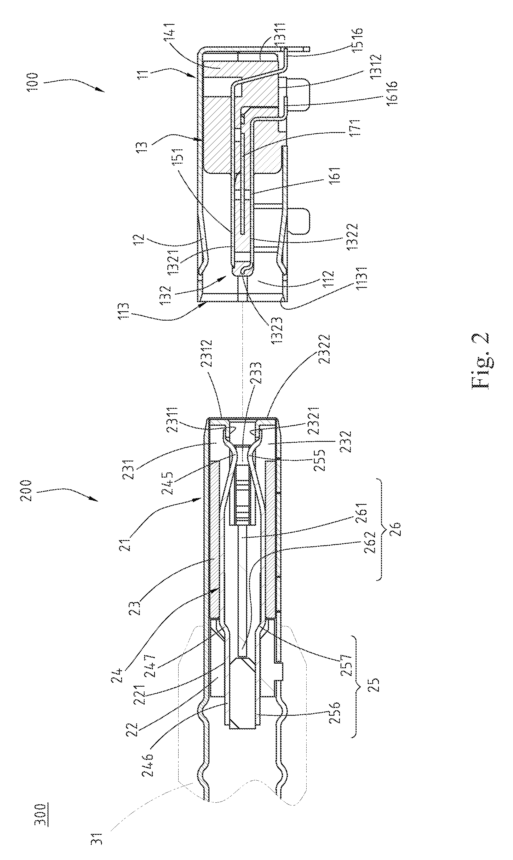
[0068]Please refer to FIG. 1, FIG. 2, and FIG. 3, illustrating exemplary embodiments of an electrical connector assembly 300 according to the instant disclosure. The electrical connector assembly 300 according to the instant disclosure comprises an electrical receptacle connector 100 and an electrical plug connector 200.

[0069]Please refer to FIG. 8, FIG. 9, FIG. 10A and FIG. 10B, in which the electrical receptacle connector 100 is in accordance with the specification of a type-C USB connection interface. In the embodiment, the electrical receptacle connector 100 comprises a first metal shell 11, a first insulation housing 13, a plurality of upper-row plate terminals 151, and a plurality of lower-row plate terminals 161.

[0070]The first metal shell 11 is a hollow shell and defines a receptacle cavity 112 therein. In the embodiment, the first metal shell 11 can be formed by bending a unitary structure. In addition, the first metal shell 11 may be provided with an elastic sheet 12 and a...


PUM


Abstract

An electrical connector assembly includes an electrical receptacle connector and an electrical plug connector. The electrical receptacle connector includes a first insulation housing, upper-row plate terminals, and lower-row plate terminals. The first insulation housing includes a first base portion and a tongue portion extending from one side of the base portion. The upper-row plate terminals and the lower-row plate terminals are at an upper surface and a lower surface of the tongue portion, respectively. The electrical plug connector includes a second insulation housing, upper-row elastic terminals, and lower-row elastic terminals. The second insulation housing includes a second base portion, an upper member, a lower member, and a mating room between the upper member and the lower member for receiving the tongue portion. The upper-row elastic terminals and the lower-row elastic terminals are respectively above and below the mating room.

Description

CROSS-REFERENCES TO RELATED APPLICATIONS[0001]This non-provisional application claims priority under 35 U.S.C. §119(a) on Patent Application No. 103110941 and 104108696, filed in Taiwan, R.O.C. on 2014 Mar. 24 and 2015 Mar. 18, the entire contents of which are hereby incorporated by reference.FIELD OF THE INVENTION[0002]The instant disclosure relates to an electrical connector, and more particularly to an electrical connector assembly provided with an electrical receptacle connector and an electrical plug connector.BACKGROUND[0003]Generally, Universal Serial Bus (USB) is a serial bus standard to the PC architecture with a focus on computer interface, consumer and productivity applications. The existing Universal Serial Bus (USB) interconnects have the attributes of plug-and-play and ease of use, from the end user's point of view. Now, as technology innovation marches forward, new kinds of devices, media formats and large inexpensive storage products are converging. They require sign...

Claims


Application Information

Patent Timeline
Patent Type & Authority Applications(United States)
IPC IPC(8): H01R13/6581H01R24/60H01R12/55H01R13/6583H01R13/52
CPCH01R13/6581H01R13/6583H01R24/60H01R13/5202H01R12/55H01R13/5219H01R13/6461H01R13/6582
Inventor KAO, YA-FENTSAI, YU-LUNHOU, PIN-YUANWANG, WEN-YUTSAI, WEN-HSIEN
Owner ADVANCED CONNECTEK INC
Why Eureka
Try Eureka