Electrical receptacle connector

a technology of electric receptacles and connectors, applied in the direction of coupling devices, two-part coupling devices, electrical apparatus, etc., can solve the problems of how to solve the above problems, interference of electromagnetic waves from different terminals during signal transmission, etc., to reduce the volume of the connector, reduce the interference of crosstalk between different pairs of differential signal terminals, and reduce the effect of resonance

Active Publication Date: 2018-09-18
ADVANCED CONNECTEK INC
View PDF2 Cites 6 Cited by
  • Summary
  • Abstract
  • Description
  • Claims
  • Application Information

AI Technical Summary

Benefits of technology

[0007]As above, the tail portions of the power terminals and the tail portions of the ground terminals have three bent portions, i.e., the first bent portion, the second bent portion, and the third bent portion. The bent portions allow the terminals to have different and non-parallel delivering paths for electromagnetic waves, so that the signals do not interfere with each other easily. Moreover, after a first bending procedure, the lower-row receptacle terminals are aligned in a same row, and the first bent portions of the lower-row receptacle terminals are spaced and aligned in a same line. The crosstalk interferences between different pairs of differential signal terminals can be reduced by using non-signal terminals neighboring to the differential signal terminals to separate the different pairs of differential signal terminals. Furthermore, problems caused by the resonance effect can also be reduced. Additionally, regarding the structure of the tail portions of the lower-row receptacle terminals, the material band and the tail portions in vertical alignment are at a same plane; namely, the material band is parallel to the tail portions. Therefore, the volume of the connector can be reduced, so that the electronic device can have still have enough space after the connector is assembled to the electronic device. Moreover, the space between the tail portions allows the tools to be inserted for processing conveniently, so that the manufacturing of the connector can be facilitated.

Problems solved by technology

The end portion of the terminal does not have bent portion, and the delivering path for electromagnetic wave cannot be changed, resulting in the interference of the electromagnetic waves from different terminals during signal transmission.
Therefore, how to solve the aforementioned problem is an issue.

Method used


Image

  • Electrical receptacle connector
  • Electrical receptacle connector
  • Electrical receptacle connector

Examples


Embodiment Construction

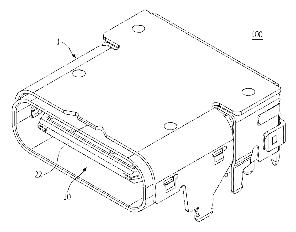
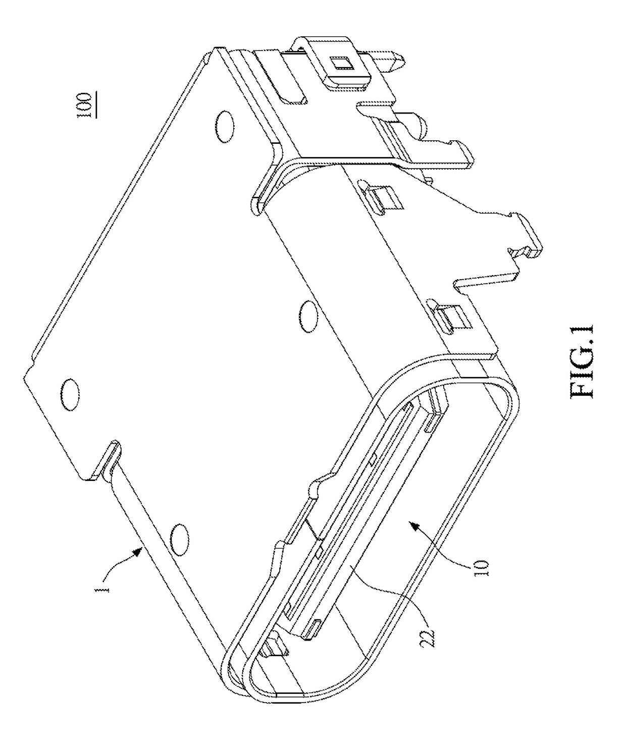
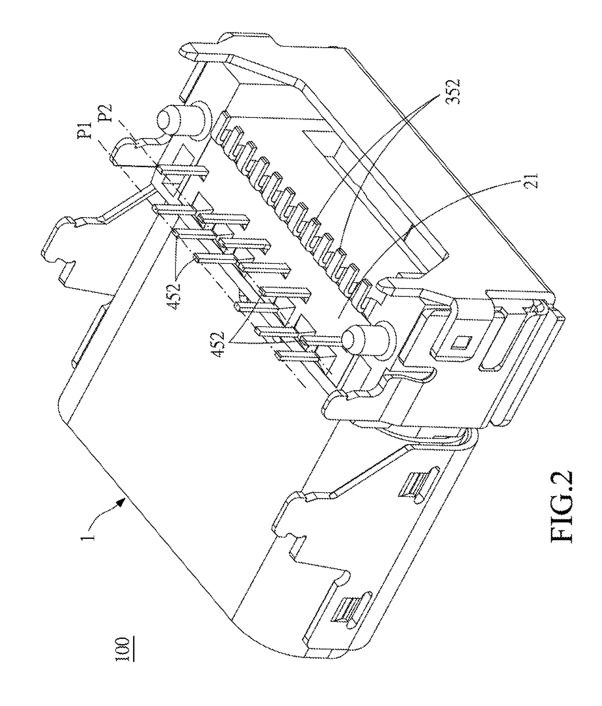
[0023]FIG. 1 illustrates a perspective view of an electrical receptacle connector of a first embodiment of the instant disclosure. FIG. 2 illustrates another perspective view of the electrical receptacle connector of the first embodiment. FIG. 3 illustrates an exploded view of the electrical receptacle connector of the first embodiment. FIG. 4 illustrates a lateral sectional view of the electrical receptacle connector of the first embodiment. Please refer to FIGS. 1 to 4, illustrating an electrical receptacle connector of a first embodiment of the instant disclosure. The electrical receptacle connector 100 can provide a reversible or dual orientation USB Type-C connector interface and pin assignments, i.e., a USB Type-C receptacle connector. In this embodiment, the electrical receptacle connector 100 comprises a metallic shell 1, an insulated housing 2, a plurality of upper-row receptacle terminals 3, and a plurality of lower-row receptacle terminals 4.

[0024]Please refer to FIGS. 1 ...


PUM


Abstract

An electrical receptacle connector includes a metallic shell, an insulated housing, upper-row receptacle terminals, and lower-row receptacle terminals. The insulated housing is in the receptacle cavity of the metallic shell. The receptacle terminals are held in the base portion and the tongue portion. The tail portions of the power terminals and the tail portions of the ground terminals have three bent portions, i.e., the first bent portion, the second bent portion, and the third bent portion. The bent portions allow the terminals to have different and non-parallel delivering paths for electromagnetic waves, so that the signals do not interfere with each other easily.

Description

CROSS-REFERENCE TO RELATED APPLICATION[0001]This non-provisional application claims priority under 35 U.S.C. § 119(a) to Patent Application No. 201610429479.X filed in China, P.R.C. on Jun. 17, 2016, the entire contents of which are hereby incorporated by reference.FIELD OF THE INVENTION[0002]The instant disclosure relates to an electrical connector, and more particular to an electrical receptacle connector.BACKGROUND[0003]Generally, Universal Serial Bus (USB) is a serial bus standard to the PC architecture with a focus on computer interface, consumer and productivity applications. The existing Universal Serial Bus (USB) interconnects have the attributes of plug-and-play and ease of use by end users. Now, as technology innovation marches forward, new kinds of devices, media formats and large inexpensive storage are converging. They require significantly more bus bandwidth to maintain the interactive experience that users have come to expect. In addition, the demand of a higher perfo...

Claims


Application Information

Patent Timeline
Patent Type & Authority Patents(United States)
IPC IPC(8): H01R24/00H01R12/72H01R13/6461H01R13/6585H01R24/60
CPCH01R12/57H01R12/58H01R13/6471H01R13/648H01R12/724H01R13/6461H01R13/6585H01R24/60
Inventor CHEN, CHING-TIENDUAN, SHU-LINWAN, WEIHONG, RUEI-SILI, JINGXU, FU-YI
Owner ADVANCED CONNECTEK INC
Why Eureka
Try Eureka