Horizontal roofing roof structure

a roof structure and horizontal technology, applied in the direction of roof drainage, roofing, building components, etc., can solve the problems of increasing the number of parts, difficulty in reducing cost, and possible water barrier property problems

Inactive Publication Date: 2015-10-01
NITTETABU STEEL SHEET CORP
View PDF12 Cites 7 Cited by
  • Summary
  • Abstract
  • Description
  • Claims
  • Application Information

AI Technical Summary

Benefits of technology

[0008]The present invention is achieved in view of the above circumstances, and an object of the present invention is to provide a horizontal roofing roof structure capable of maintaining the water barrier property without the decorative member.

Problems solved by technology

However, since the folded part and the flashing part have simply upwardly folded structures, when a large amount of rain water is introduced to the throating plate, a problem in a water barrier property might occur.
However, a roof structure disclosed in the patent literature 1 requires the decorative member, which causes an increase in the number of parts and thus makes it difficult to reduce cost, as well as takes more labor.

Method used


Image

  • Horizontal roofing roof structure
  • Horizontal roofing roof structure
  • Horizontal roofing roof structure

Examples


Embodiment Construction

[0019]The following description is made to an embodiment according to the present invention with referring to attached drawings.

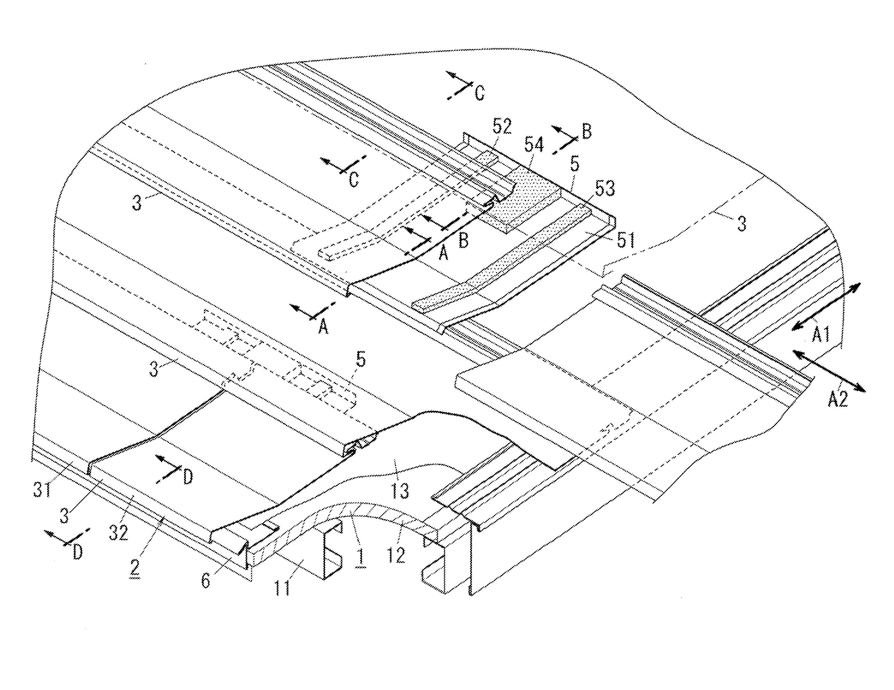
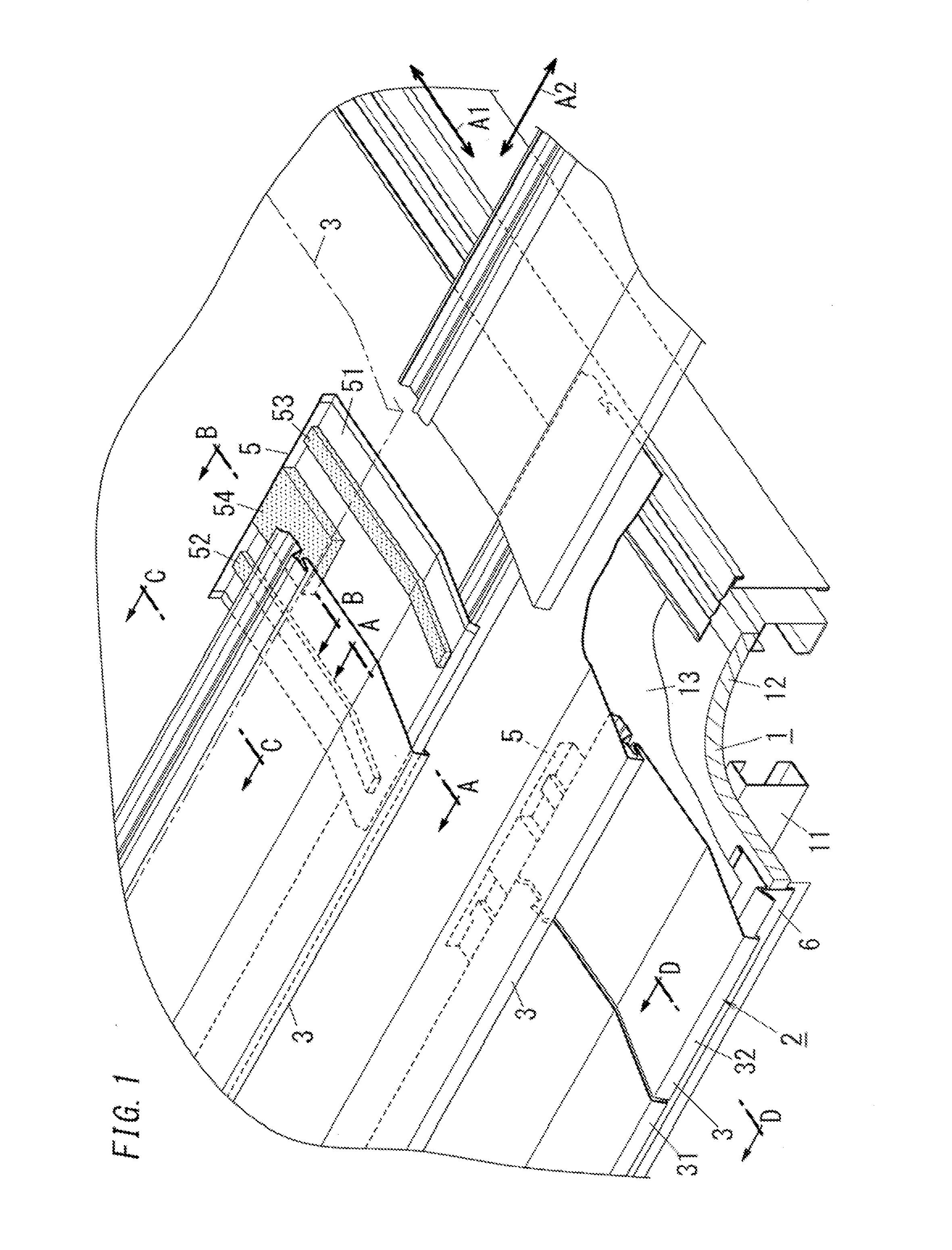
[0020]A horizontal roofing roof structure of the embodiment is for example applied to a roofing structure such as a gable roof, a hipped roof, and a penthouse roof. A roof is provided on a top part of a building. The roof is inclined. An inclining direction of the roof (a direction parallel to an arrow A1 in FIG. 1, hereinafter, referred to as a roof pitch direction) is defined as a direction parallel to an eave-ridge direction. In other words, the roof pitch direction is defined as a direction parallel to a rain flowing direction (a water-flow direction) on the roof. Also, a direction perpendicular to the roof pitch direction is defined as a lateral direction (i.e. a ridge direction, a direction parallel to an arrow A2 in FIG. 1).

[0021]In the embodiment, a “ridge” is defined as the highest part of a surface of the roof. Therefore, according to the embodime...


PUM


Abstract

Provided is a horizontal roofing roof structure need not include a decorative member, necessary for the conventional horizontal roofing roof structures in order to maintain water barrier property, while maintaining water barrier property. This horizontal roofing roof structure includes a first lateral roofing material, a second lateral roofing, and an inner gutter disposed below adjacent ends of the first lateral roofing material and the second lateral roofing material. The inner gutter includes a body part, a first seal that is provided on part, facing the first lateral roofing material, of the body part so as to extend along an end in a lengthwise direction of the first lateral roofing material and abuts a lower surface of the first lateral roofing material, a second seal that is provided on part, facing the second lateral roofing material, of the body part so as to extend along an end in a lengthwise direction of the second lateral roofing material and abuts a lower surface of the second lateral roofing material, and a third seal that is provided on part, between the first seal and the second seal, of the body part, and abuts both an end, on a upstream side in a roof pitch direction, of the first lateral roofing material and an end, on the upstream side in the roof pitch direction, of the second lateral roofing material.

Description

TECHNICAL FIELD[0001]The invention relates to horizontal roofing roof structures.BACKGROUND ART[0002]JP 2006-183265A (hereafter, referred to as patent literature 1) discloses a conventional horizontal roofing roof structure.[0003]In the horizontal roofing roof structure disclosed in the patent literature 1, a plurality of horizontally roofing cladding materials are connected to each other in a direction (a lateral direction) perpendicular to a roof pitch direction (an eave-ridge direction in the patent literature 1). A lengthwise direction of a horizontally roofing cladding material is substantially parallel to the lateral direction.[0004]An end in the lengthwise direction of the horizontally roofing cladding material is connected to an end in the lengthwise direction of an adjacent horizontally roofing cladding material. A throating plate is attached below the adjacent ends of the horizontally roofing cladding materials. A folded part, which is part bent towards a front surface, is...

Claims


Application Information

Patent Timeline
Patent Type & Authority Applications(United States)
IPC IPC(8): E04D1/36E04D13/04E04D1/12
CPCE04D1/365E04D13/0481E04D1/12E04D3/365E04D3/366E04D13/158E04D2013/0468E04D1/2918E04D1/2942
Inventor NAWATE, TETSU
Owner NITTETABU STEEL SHEET CORP
Why Eureka
Try Eureka