Roof flashing for a pipe or duct

a technology for flashing and ducts, applied in the direction of roofs, building components, building insulations, etc., can solve the problems that flashing should be produced in an uncomplicated and economically efficient manner, and achieve the effect of simple manufacturing

Inactive Publication Date: 2017-02-02
TUOTE
View PDF2 Cites 2 Cited by
  • Summary
  • Abstract
  • Description
  • Claims
  • Application Information

AI Technical Summary

Benefits of technology

[0019]Considerable advantages are obtained by the present invention. The flashing is compact and can be fixedly attached to the roof by means of screw fastening. Subsequently, the pipe or duct can be installed in a substantially vertical position due the angle of inclination of the plane of the opening of the collar. According to the invention, a single flashing can be used for different roofs each having a different pitch angle due to a combination of the shape of the collar, namely the oblong shape of the opening, and the inclination angle of the plane of the opening. Preferably, the flashing according to the invention is used with a prior art pipe having a tightly connected, preferably integral, dome shaped part for overlapping the collar. The pipe may thereby be supported by the flashing where the dome-shaped part contacts the collar.

Problems solved by technology

Such flashing should be produced in an uncomplicated and economically efficient manner on an industrial scale.

Method used


Image

  • Roof flashing for a pipe or duct
  • Roof flashing for a pipe or duct
  • Roof flashing for a pipe or duct

Examples


Embodiment Construction

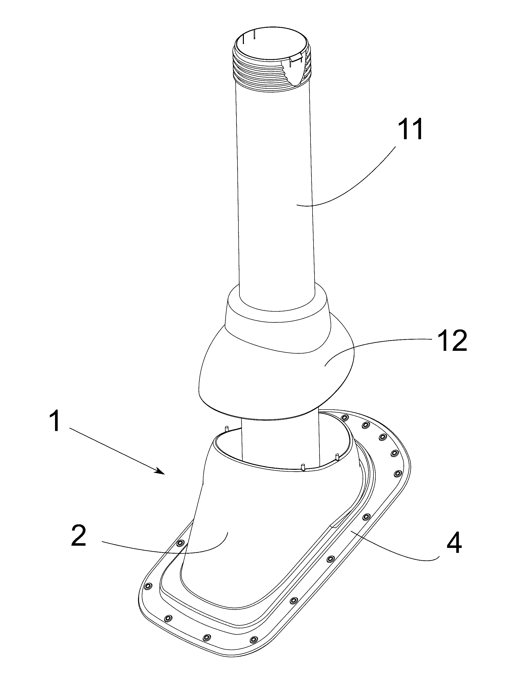
[0026]The flashing is particularly designed for a seamed roof or for a roofing element shaped as a seamed roof. The mounting of the flashing may be carried out rapidly due to the simple and compact structure. The same flashing may be used for various roofs, each having a different pitch.

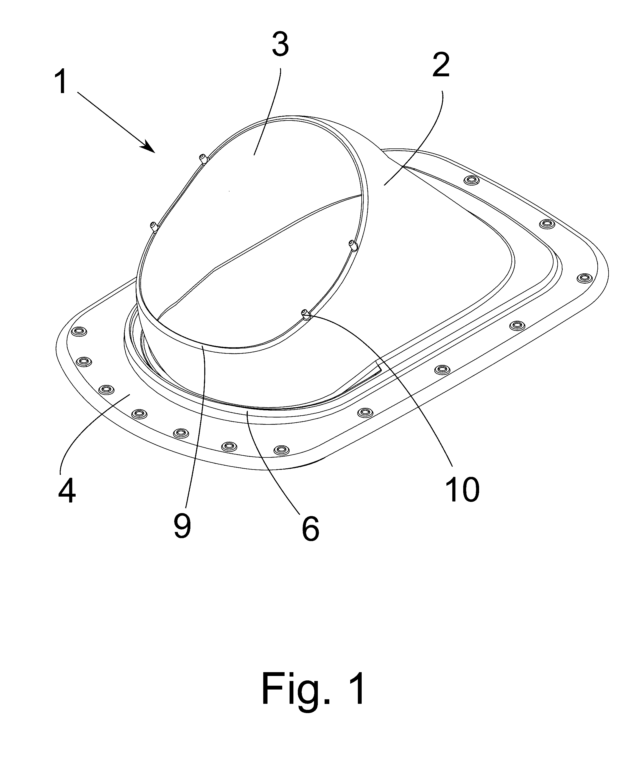
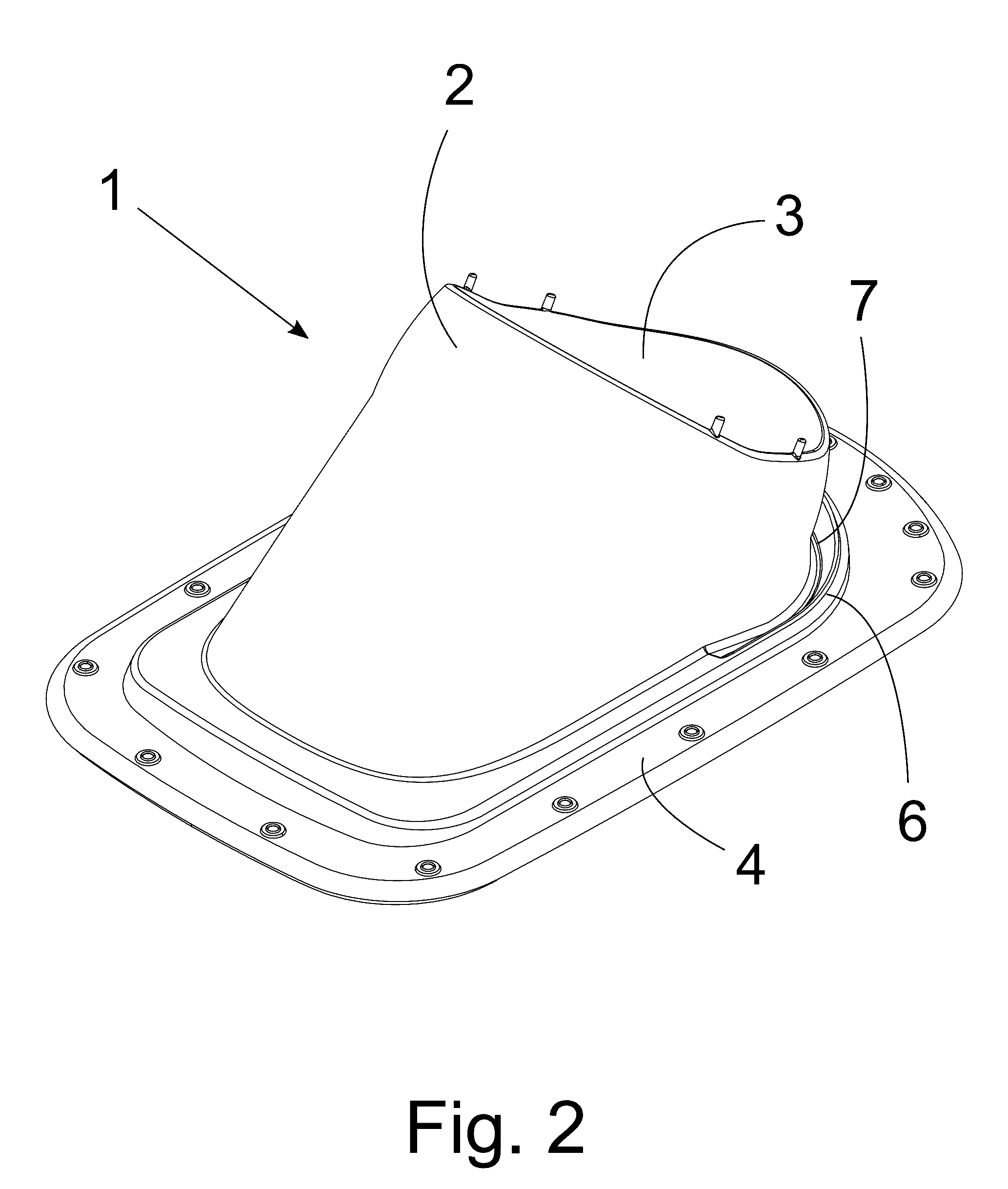
[0027]FIG. 1 shows a first perspective view of a flashing 1 according to at least some embodiment of the flashing 1 according to the present invention. The flashing 1 comprises collar 2 having an oblong opening 3 for a pipe duct (not shown), and a substantially planar flange 4. Collar 2 is thus formed, that the flashing 1 may be used for any roof pitch in the range 13° to 50°. In other words, the flashing 1 may be used for various seamed roofs having a pitch in the mentioned range, for example 35°. The oblong shape of opening 3 facilitates this. The plane defined by the upper and lower edges of opening 3 is inclined by an angle α which is in the range 25°-35° relative to the plane defined by flange 4...


PUM


Abstract

The invention relates to a flashing for a pipe or duct passing through a seamed roof. The flashing comprises a collar at the upper end of which is provided an opening for the pipe or duct, and a substantially flat flange to which the lower end of the collar is joined, which flange is configured to be attached to a portion of a roof, whereby a plane through the upper and lower edges of the opening in the upper end of the collar is set inclined by an angle in a range between 25° and 35° relative to the plane defined by the flange. The opening at the upper end of the collar has an oval or oblong shape, facilitating the use of the flashing at various roof pitch angles without the collar being modified.

Description

TECHNICAL FIELD[0001]The invention relates to a flashing for a pipe or duct passing through a roof. In particular, the invention relates to a flashing for a pipe or duct passing through a seamed roof.TECHNICAL BACKGROUND[0002]A building is often provided with leadthroughs, or openings for ducts and pipes passing through the roof of the building. The leadthroughs represent discontinuities in the weatherproofing roofing material and are commonly designed to preserve the tightness of the roof to water and snow. For this reason, various structures have been developed for sealing roof leadthroughs, exit openings and the like.[0003]For example in international patent application WO 2004 / 003311 is disclosed a flashing for a roof having a profiled roofing, in particular for a roof assembled from profiled roofing elements, whereby the flashing comprises a collar surrounding the duct and a flange connecting to the roofing. The flange is designed to be mounted beneath the roofing element in su...

Claims


Application Information

Patent Timeline
Patent Type & Authority Applications(United States)
IPC IPC(8): E04D13/147E04B1/68E04B1/64
CPCE04D13/1476E04B1/68E04B1/64E04D13/147E04D13/1471E04D1/30E04D1/36
Inventor SAIKKONEN, EERO
Owner TUOTE
Why Eureka
Try Eureka