
Roof vent pipe shield

a technology for vent pipes and shields, applied in ventilation systems, building repairs, heating types, etc., can solve problems such as flashing deterioration, flashing leakage, and flashing deterioration where it contacts the pipe, and achieve the effect of preventing flashing leakage, preventing flashing leakage, and preventing flashing leakag

Active Publication Date: 2011-09-15
MANNING MARK STEPHEN
View PDF16 Cites 3 Cited by
  • Summary
  • Abstract
  • Description
  • Claims
  • Application Information

AI Technical Summary

Problems solved by technology

Studies have shown that in as little as 6 or 7 years, the flashing can deteriorate where it contacts the pipe and begin to leak due to the exposure to the elements.
In addition, animals such as mammals, birds, reptiles, and the like may damage the flashing integrity while nesting, feeding, or the like.
In states where there is a raised crown surrounding the base used for the flashing around the vent stack pipe, it is quite common that the flashing leaks begin at the intersection where the vent pipe enters the crown.
When the flashing begins to leak, the building owner is faced with either replacing the entire vent which is an expensive and probably prohibitive procedure, or use one of a number of covers.
A number of covers have been available for covering the leaking roof vent stack, however, the current ones all suffer from problems such as the need to have multiple sizes, ones to accommodate different roof pitches and attachment means which are readily susceptible to leaking.
Because vent stacks are not cut to exact standard sizes, they vary in height by a large amount and covers of a specific height are difficult to install, if not impossible in some cases to use.
In the case where there is a raised crown surrounding the base, many of the solutions will not work at all since they are designed to be used with a flat base, and will not work with a raised base.
The end cap does not appear to be secured and is sufficiently small that it can be blown off the device in high winds.

Method used


Image

  • Roof vent pipe shield
  • Roof vent pipe shield
  • Roof vent pipe shield

Examples


Embodiment Construction

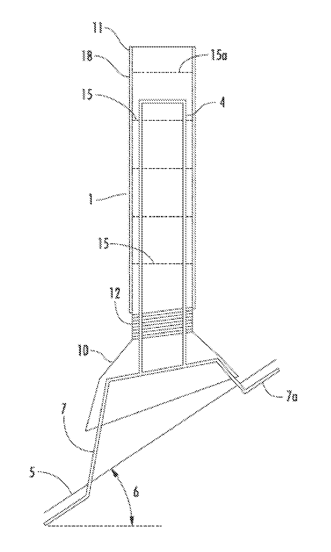
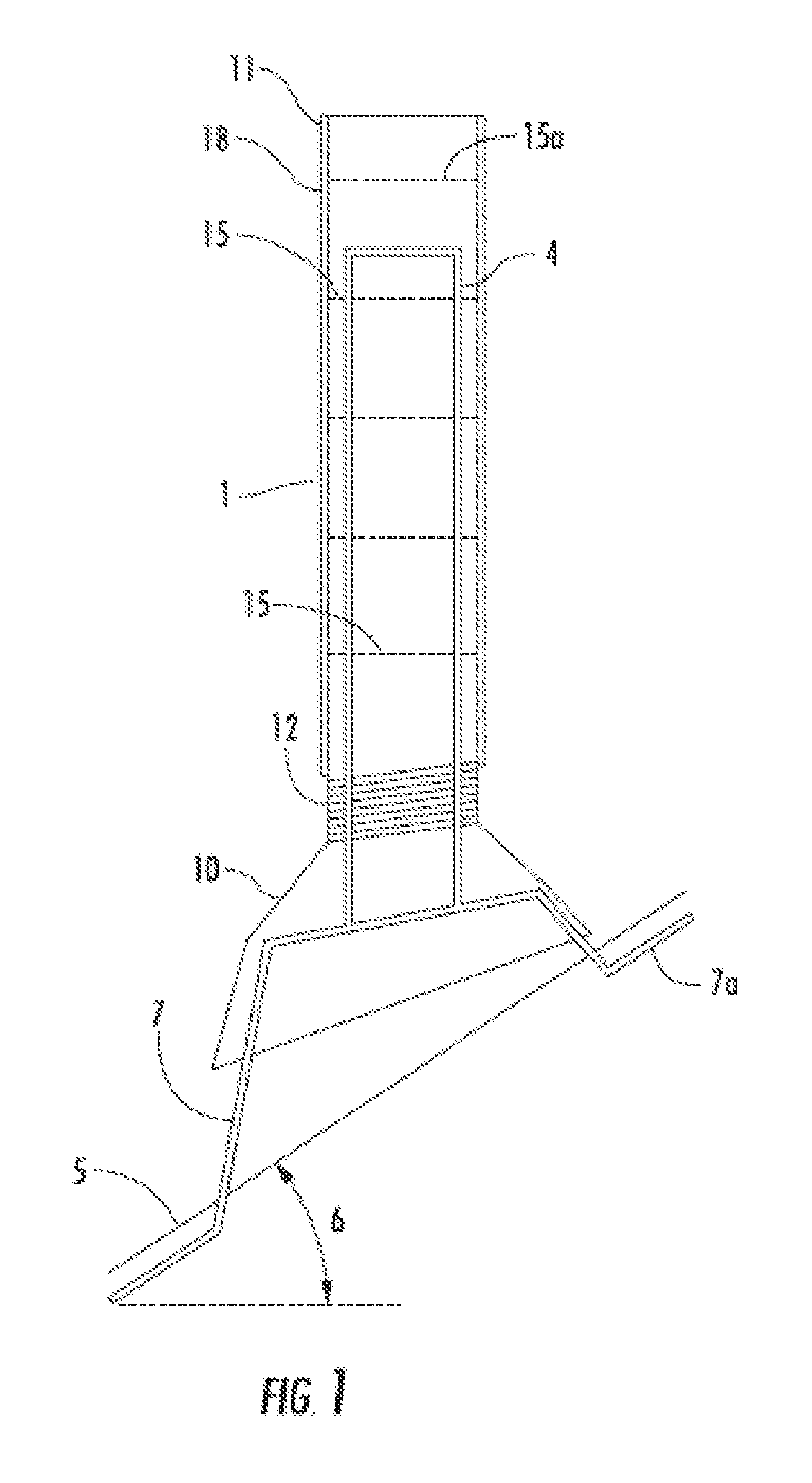
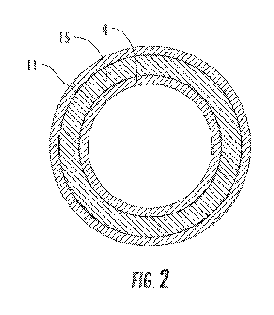
[0035]While this invention is susceptible to embodiment in many different forms, there is shown in the drawings and will herein be described in detail specific embodiments, with the understanding that the present disclosure of such embodiments is to be considered as an example of the principles and not intended to limit the invention to the specific embodiments shown and described. In the description below, like reference numerals are used to describe the same, similar or corresponding parts in the several views of the drawings. This detailed description defines the meaning of the terms used herein and specifically describes embodiments in order for those skilled in the art to practice the invention.

[0036]The terms “a” or “an”, as used herein, are defined as one or as more than one. The term “plurality”, as used herein, is defined as two or as more than two. The term “another”, as used herein, is defined as at least a second or more. The terms “including” and / or “having”, as used he...


PUM


Abstract

The present invention relates to a vent pipe protection cover for repairing damaged flashing or for any new construction for waterproofing the vent pipe. A two piece construction which allows one device to accommodate roof pitches and various size vent pipes without the need to custom make the device is disclosed.

Description

COPYRIGHT NOTICE[0001]A portion of the disclosure of this patent contains material that is subject to copyright protection. The copyright owner has no objection to the reproduction by anyone of the patent document or the patent disclosure as it appears in the Patent and Trademark Office patent files or records, but otherwise reserves all copyright rights whatsoever.BACKGROUND OF THE INVENTION[0002]1. Field of the Invention[0003]The present invention relates to plumbing vent stacks that extend above the roof on a building for venting of sewer gases. In particular, the present invention relates to a vent pipe protective cover for protecting the vent pipe when installed over the vent stack.[0004]2. Description of Related Art[0005]A vent stack protrudes from the roof deck of a building with toilet facilities to vent and remove the sewer gases from the sewer trap. The vent stack is normally installed at the time the building is built, integrated into the roof as it is installed and seale...

Claims


Application Information

Patent Timeline
IPC IPC(8): E04B1/684
CPCE04D13/1471F24F7/02E04D13/1476
Inventor MANNING, MARK STEPHEN
Owner MANNING MARK STEPHEN
Learn More