
Truss spacing devices

a technology of spacing devices and trusses, which is applied in the direction of girders, joists, building roofs, etc., can solve the problems of high risk of roof trusses, inaccurate measurements, and warping of preacher blocks, so as to safely and quickly space trusses

Inactive Publication Date: 2007-03-15
STALLING ADAM R
View PDF14 Cites 3 Cited by
  • Summary
  • Abstract
  • Description
  • Claims
  • Application Information

AI Technical Summary

Benefits of technology

[0006] The primary object of the present invention is to provide a truss spacing device that permits a person to safely and quickly space trusses on construction sites.
[0007] A further object of the present invention is to provide a truss spacing device that is durable.
[0008] An even further object of the present invention is to provide a truss spacing device that is lightweight.
[0009] Another object of the present invention is to provide a truss spacing device that is compact.
[0010] A further object of the present invention is to provide a truss spacing device that is versatile.
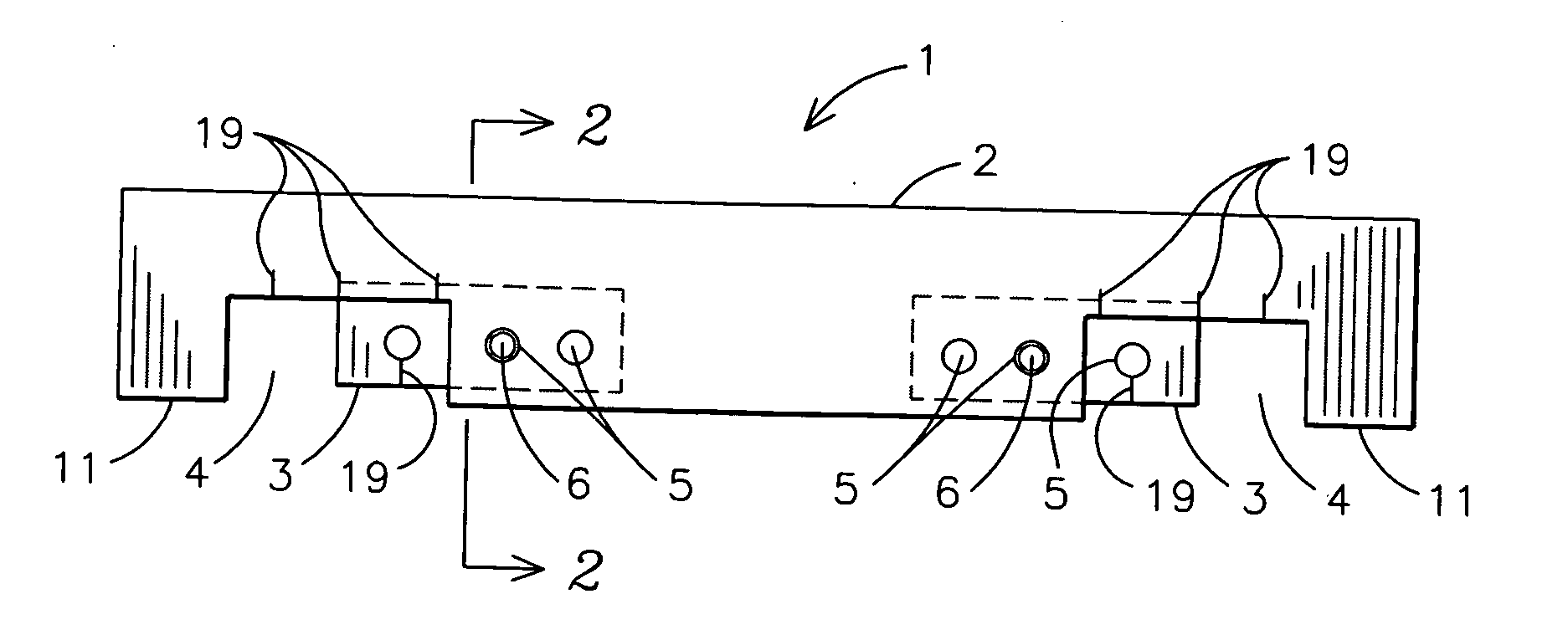
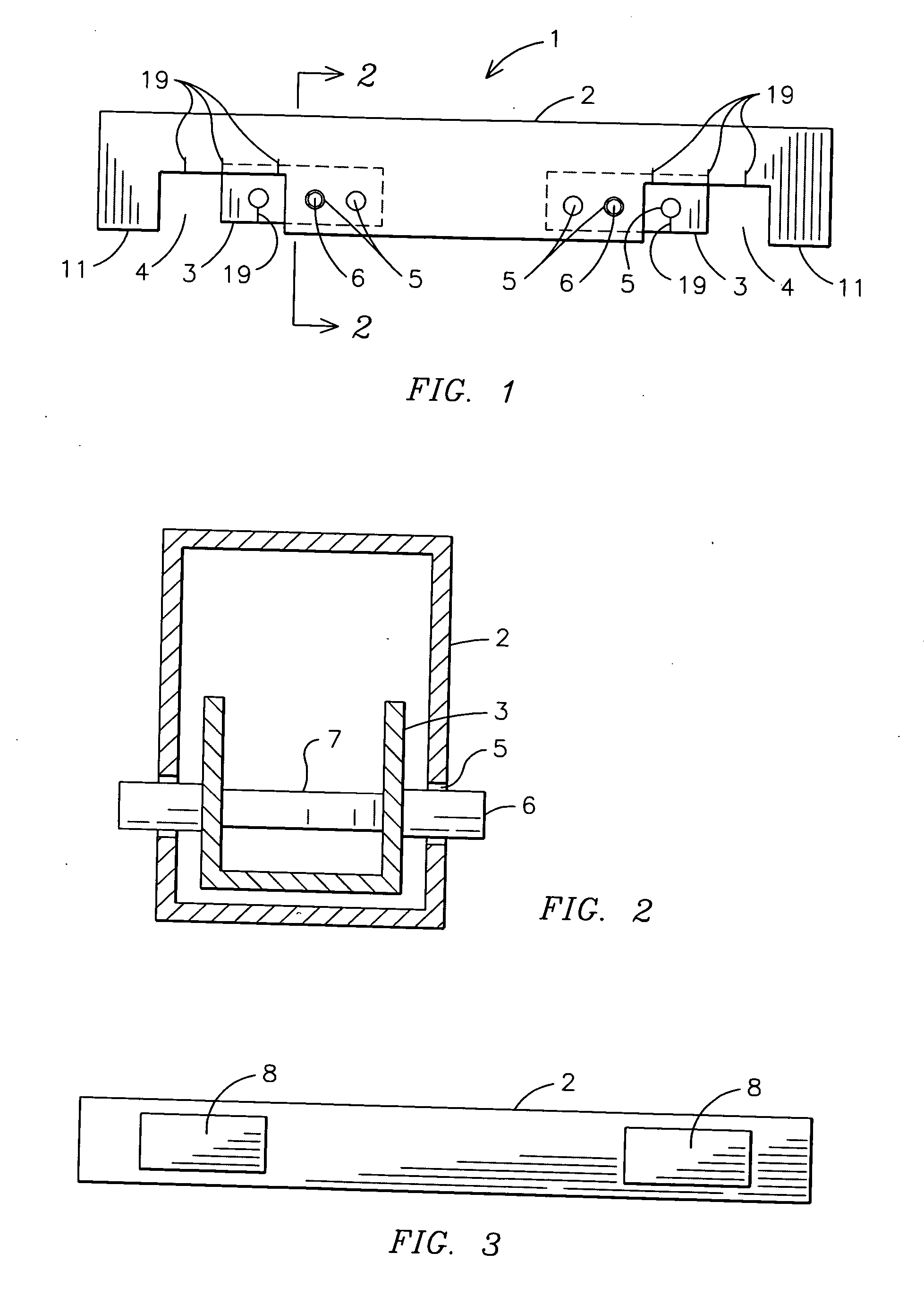
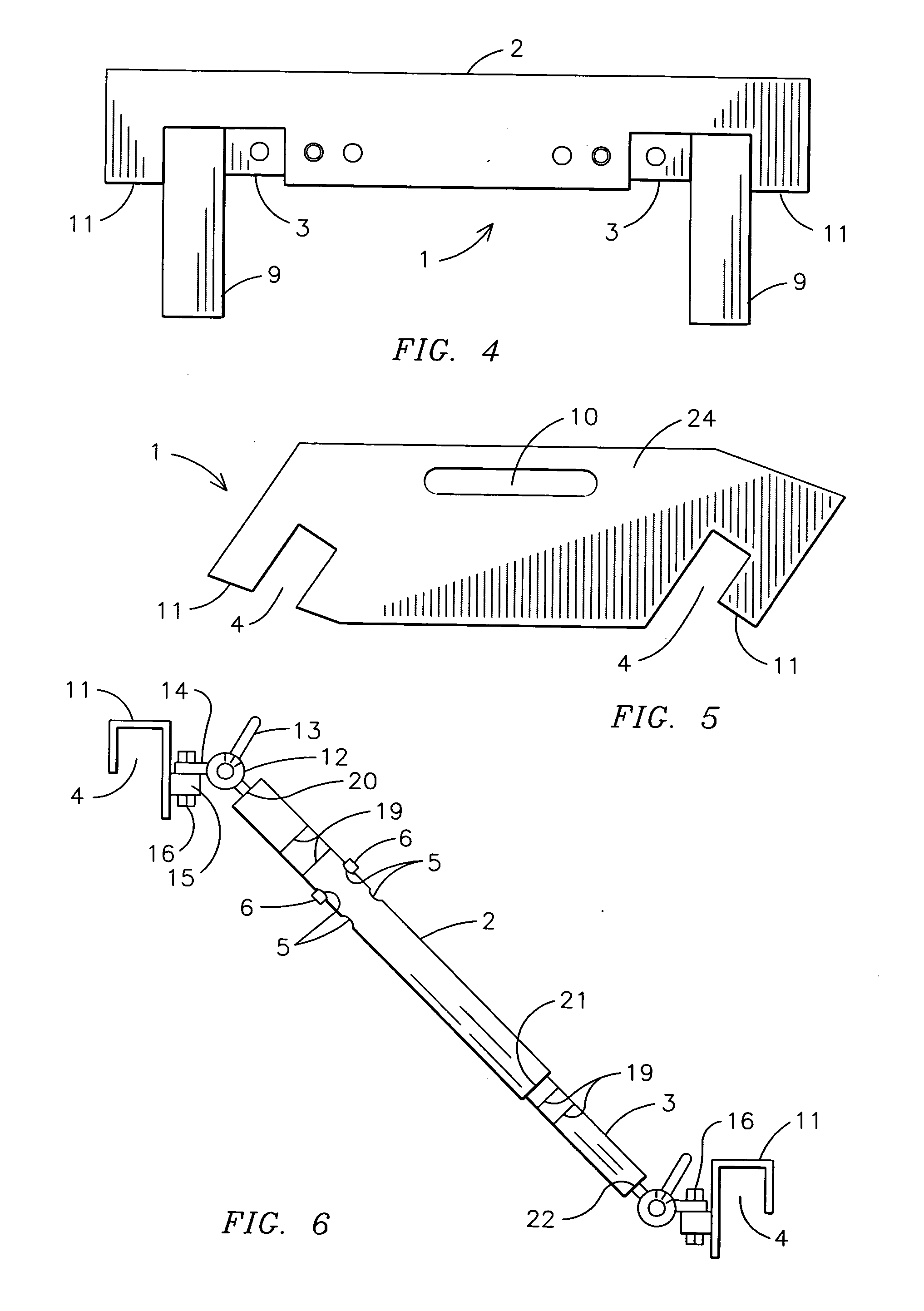
[0012] The present invention fulfills the above and other objects by providing a truss spacing device having an outer body section and at least one inner body section extendably housed within the outer body section wherein a truss accommodation area is formed between a truss holding leg and the inner body section. To use the device, a person adjusts the inner body sections so as to correspond with the appropriate width of a truss and locks the inner body section in place. Then, he or she grasps the truss and places the truss in the truss accommodation areas. He or she may then hammer the top of the outer body section so as to secure the truss in the truss accommodation area. Finally, a person positions the truss at the desired location on a tie beam for securement. The outer body may include markings or be color-coded so as to permit the user to easily determine adjust the truss spacing device to accommodate the truss at hand.

Problems solved by technology

Thus, setting roof trusses is a highly dangerous job.
As preacher blocks are merely 2×4 wood pieces, the preacher blocks tend to warp and break over time.
The usage of a warped preacher block leads to inaccurate measurements, which is detrimental to the integrity of a roof.

Method used


Image

  • Truss spacing devices
  • Truss spacing devices
  • Truss spacing devices

Examples


Embodiment Construction

[0025] For purposes of describing the preferred embodiment, the terminology used in reference to the numbered components in the drawings is as follows: [0026]1. truss spacing device, generally [0027]2. outer body section [0028]3. inner body section [0029]4. truss accommodation area [0030]5. hole [0031]6. button [0032]7. spring section [0033]8. rubber panel [0034]9. truss section [0035]10. handle [0036]11. truss holding leg section [0037]12. dial [0038]13. lever section [0039]14. angle adjuster extension [0040]15. truss holding leg extension [0041]16. nut [0042]17. roof pitch [0043]18. building [0044]19. markings [0045]20. first end of outer body [0046]21. second end of outer body [0047]22. first end of inner body [0048]23. second end of inner body

[0049] With reference to FIG. 1, a side plan view of a first embodiment of a truss spacing device of the present invention is shown. The truss spacing devices 1 includes an outer body section 2 and two inner body sections 3. The outer body...


PUM


Abstract

Truss spacing devices (1) having truss holding legs (11) and truss accommodation areas (4) are provided. One embodiment has an outer body section (2) and at least one inner body section (3) extendably housed within the outer body section (2). A truss accommodation area (4) is formed between the truss holding leg (11) and the inner body section (3). To use, a person adjusts the inner body sections (3) so as to correspond with the appropriate width of a truss (9) and locks the inner body sections (3) in place. Then, the user places the truss (9) in the truss accommodation areas (4). Finally, a person positions the truss (9) at the desired location on a tie beam for securement. Alternate embodiments of the present invention allow for the use of the truss spacing device (1) in conjunction with roof pitches (17).

Description

BACKGROUND OF THE INVENTION [0001] This invention relates to truss spacing devices, more particularly, truss spacing devices that permit a person to safely and quickly space trusses on construction sites. [0002] When setting roof trusses, a crane lifts the trusses to an area on top of the roof beams where construction workers are located. The workers must then grab the trusses that are hanging from the crane and properly position the trusses on a tie beam, typically about 2 feet off center, for securement. Meanwhile, the workers must maintain their balance so as to not fall off the roof beams, be cautious of the location of the trusses so as not to get hit by the trusses, measure the proper distance for the securement of the trusses to the tie beam, hold down and finally nail the trusses to the tie beam. Thus, setting roof trusses is a highly dangerous job. In addition, more than one worker is usually required for setting the trusses in order to correctly and hopefully safely secure...

Claims


Application Information

Patent Timeline
IPC IPC(8): E04C3/02
CPCE04B7/02E04G21/1891E04C2003/026
Inventor STALLING, ADAM R.
Owner STALLING ADAM R
Learn More