Variable displacement swash plate compressor

Active Publication Date: 2015-10-01
TOYOTA IND CORP
View PDF6 Cites 0 Cited by
  • Summary
  • Abstract
  • Description
  • Claims
  • Application Information

AI Technical Summary

Benefits of technology

[0012]It is an object of the present invention to provide a compact compressor ha

Problems solved by technology

Although the non-rotation movable body moves in the control pressure chamber along the rotation axis of the drive shaft, the non-rotation movable body is not allowed to rotate about the rotation axis of the drive shaft.
This may result in insufficient lubrication around the non-rotation movable body and adversely affect the movement characteristics of the actuator.
In such a case, it may become difficult to change the inclination angle of the swash plate adequately, and the compressor displacement may not be controlled in the preferred manner by lengthening and shortening the piston stroke.
Further, in this compressor, wear or the like is apt

Method used


Image

  • Variable displacement swash plate compressor
  • Variable displacement swash plate compressor
  • Variable displacement swash plate compressor

Examples


Example

First Embodiment

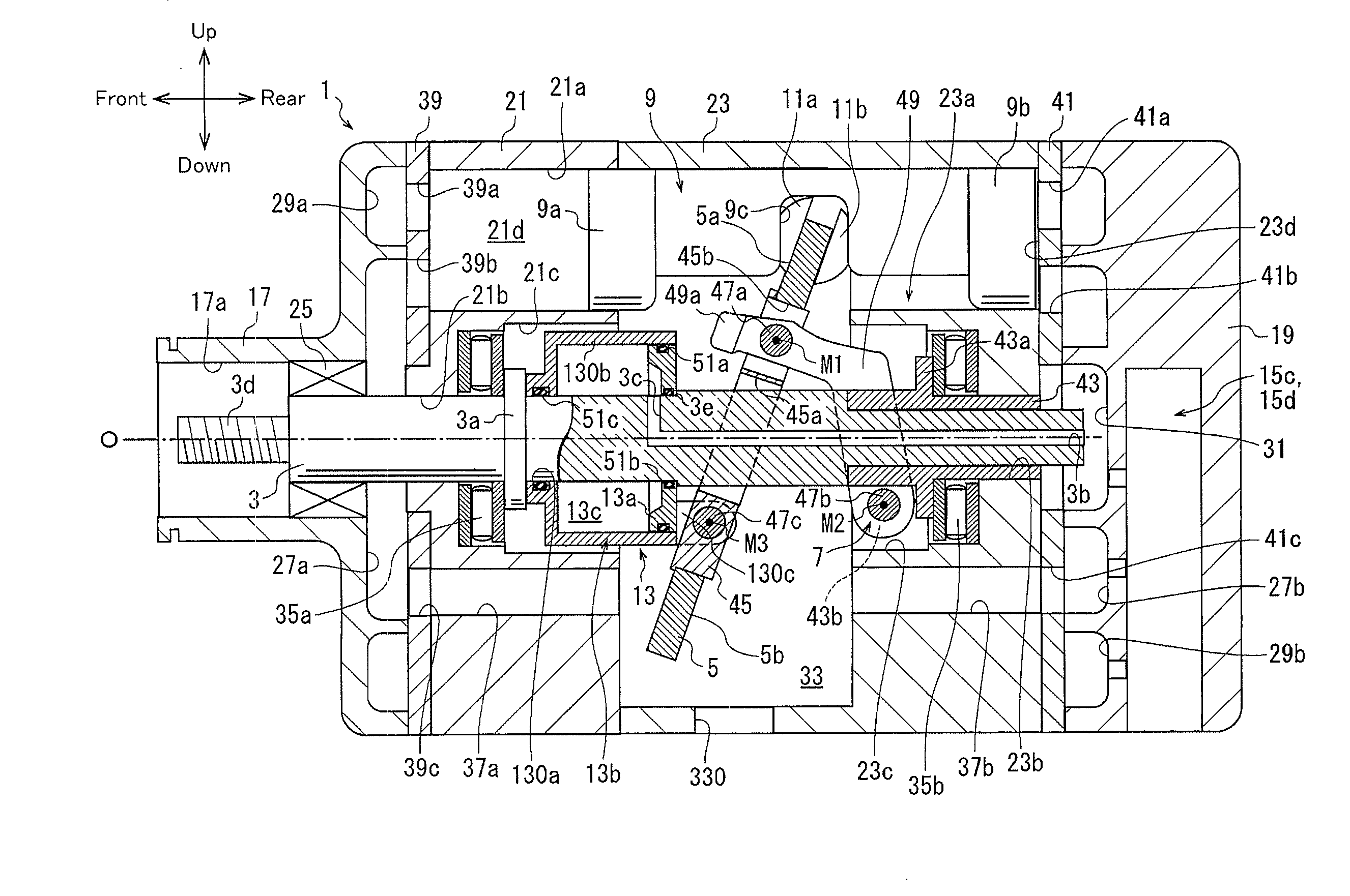
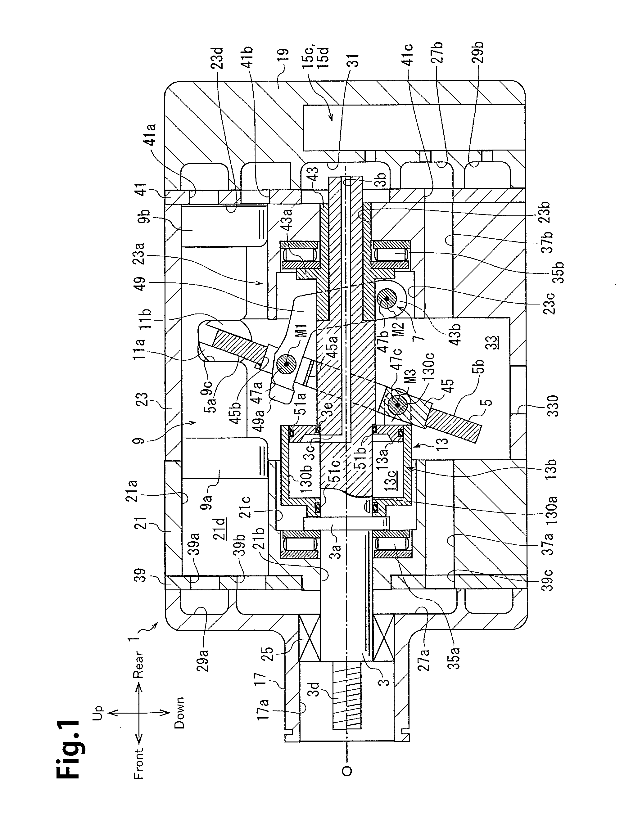
[0023]Referring to FIGS. 1 and 3, a compressor of the first embodiment includes a housing 1, a drive shaft 3, a swash plate 5, a link mechanism 7, pistons 9, front and rear shoes 11a and 11b, an actuator 13, and a control mechanism 15, which is shown in FIG. 2. Each piston 9 is provided with a pair of the shoes 11a and 11b.

[0024]As shown in FIG. 1, the housing 1 includes a front housing member 17, which is located at the front of the compressor, a rear housing member 19, which is located at the rear of the compressor, and first and second cylinder blocks 21 and 23, which are located between the front housing member 17 and the rear housing member 19.

[0025]The front housing member 17 includes a boss 17a, which projects toward the front. A sealing device 25 is arranged in the boss 17a around the drive shaft 3. Further, the front housing member 17 includes a first suction chamber 27a and a first discharge chamber 29a. The first suction chamber 27a is located in a radial...

Example

Second Embodiment

[0084]A compressor of the second embodiment includes a control mechanism 16 shown in FIG. 4 instead of the control mechanism 15 used in the compressor of the first embodiment. The control mechanism 16 includes a bleed passage 16a, a gas supplying passage 16b, a control valve 16c, and an orifice 16d. The bleed passage 16a and the gas supplying passage 16b form a control passage.

[0085]The bleed passage 16a is connected to the pressure regulation chamber 31 and the second suction chamber 27b. Thus, the control pressure chamber 13c and the second suction chamber 27b are in communication with each other through the bleed passage 16a. The gas supplying passage 16b is connected to the pressure regulation chamber 31 and the second discharge chamber 29b. Thus, the control pressure chamber 13c and the pressure regulation chamber 31 are in communication with the second discharge chamber 29b through the gas supplying passage 16b. The gas supplying passage 16b includes the orifi...

Example

Third Embodiment

[0092]Referring to FIGS. 5 and 6, a compressor of the third embodiment includes a housing 10 and pistons 90 instead of the housing 1 and the pistons 9 used in the compressor of the first embodiment.

[0093]The housing 10 includes a front housing member 18, a rear housing member 19 similar to that of the first embodiment, and a second cylinder block 23 similar to that of the first embodiment. The front housing member 18 includes a boss 18a, which extends toward the front, and a recess 18b. A sealing device 25 is arranged in the boss 18a. The front housing member 18 differs from the front housing member 17 of the first embodiment in that the front housing member 18 does not include the first suction chamber 27a and the first discharge chamber 29a.

[0094]In the compressor, a swash plate chamber 33 is defined in the front housing member 18 and the second cylinder block 23. The swash plate chamber 33, which is located in the middle portion of the housing 10, is in communica...


PUM


Abstract

A variable displacement swash compressor includes a housing, a drive shaft, a swash plate, a link mechanism, a piston, a conversion mechanism, an actuator, and a control mechanism. The swash plate is rotatable together with the drive shaft in a swash plate chamber. The conversion mechanism reciprocates the piston in a cylinder bore. The actuator is operative to change the inclination angle of the swash plate. The actuator is rotatable integrally with the drive shaft. The actuator includes a partitioning body, a movable body, and a control pressure chamber. The control mechanism changes the pressure of the control pressure chamber to move the movable body. The movable body and the link mechanism are located at opposite sides of the swash plate.

Description

BACKGROUND OF THE INVENTION[0001]The present invention relates to a variable displacement swash plate compressor.[0002]Japanese Laid-Out Patent Publication Nos. 5-172052 and 52-131204 describe conventional variable displacement swash plate compressors (hereafter simply referred to as the compressors). The compressors each have a housing including a suction chamber, a discharge chamber, a swash plate chamber, and a plurality of cylinder bores. A rotatable drive shaft is supported in the housing. A swash plate that is rotatable together with the drive shaft is arranged in the swash plate chamber. A link mechanism is located between the drive shaft and the swash plate to allow the inclination angle of the swash plate to change. The inclination angle refers to an angle relative to a direction orthogonal to the rotation axis of the drive shaft. Each cylinder bore accommodates a piston. The piston reciprocates in the cylinder bore and defines a compression chamber in the cylinder bore. A ...

Claims


Application Information

Patent Timeline
IPC IPC(8): F04B27/20F04B27/08
CPCF04B27/0804F04B27/20F04B27/1054F04B27/1063F04B27/1072F04B27/1804F04B2027/1813F04B2027/1886F04B27/08F04B27/14
Inventor YAMAMOTO, SHINYASUZUKI, TAKAHIROHONDA, KAZUNARINISHII, KEIYAMAZAKI, YUSUKEOTA, MASAKI
Owner TOYOTA IND CORP
Why Eureka
Try Eureka