
Adhesive film functionalizing color compensation and near infrared ray (NIR) blocking and plasma display panel filter using the same

Inactive Publication Date: 2007-11-15
LG CHEM LTD
View PDF11 Cites 5 Cited by
  • Summary
  • Abstract
  • Description
  • Claims
  • Application Information

AI Technical Summary

Benefits of technology

[0016] It is an aspect of the present invention to provide an adhesive film functionalizing color compensation and near infrared ray blocking, having superior durability with little transmittance change at high temperature and humidity, having superior thermal stability, being capable of maintaining transmittance in the visible region for an extended time, and having good near infrared ray blocking performance.
[0017] It is another aspect of the present invention to provide a plasma display panel filter comprising an adhesive film having color compensation and near infrared ray blocking performance without an additional adhesive layer and thus being capable of simplifying the film, and a plasma display panel comprising the same.

Problems solved by technology

However, the rubber adhesives have poor aging resistance, the poly(vinyl ether) adhesives have poor heat resistance, and the silicone adhesives have a disadvantage in adhesivity.
But this fluidity tends to lower heat resistance or moisture resistance of the dye included in the adhesive to improve color compensation or near infrared ray blocking performance.
However, Korea Patent Publication No. 2002-0055410 makes no mention of an adhesive structure and composition, and Korea Patent Publication No. 2004-0049280 does not suggest near infrared blocking efficiency regarding a near infrared ray absorption film.
And Japan Patent Publication No. 2001-207142 does not suggest a cyanine-based NIR dye and a cyanine-based neon-cut dye, but weak heat-resistance and light-resistance occur when cyanine dye alone is used.
In addition, it is costly and ineffective to stack these films to manufacture a PDP filter.
Thus, there have been attempts to develop adhesive layers, such as an adhesive layer including a neon-cut layer and an adhesive layer including a near infrared ray blocking layer, but durability at high temperature and humidity has been shown to be unsatisfactory.
It is also costly and ineffective to stack the films such as binder, a color compensation layer, a near infrared ray blocking layer, and an adhesive layer, individually, to manufacture a PDP filter according to the conventional methods.

Method used


Image

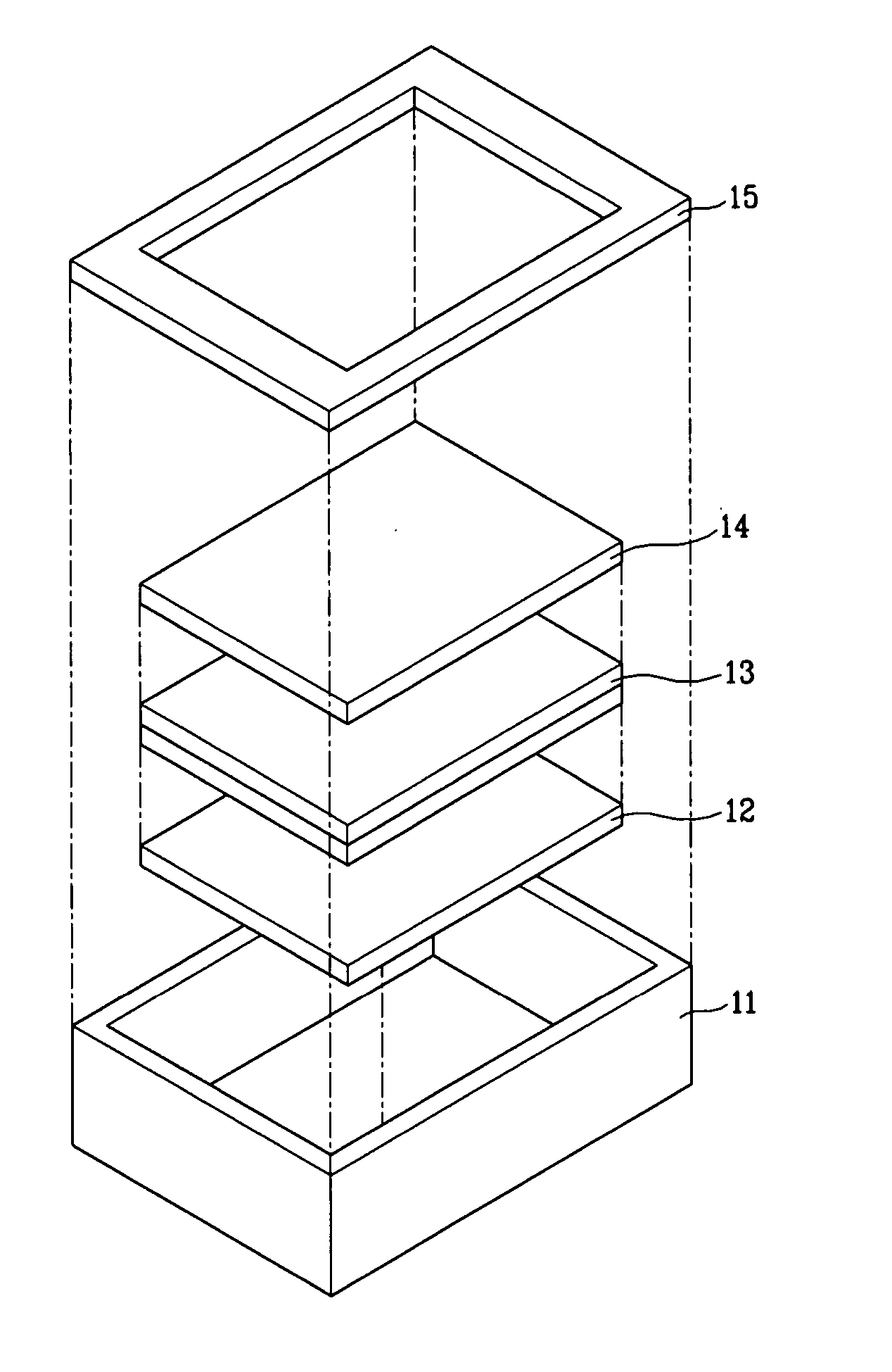
  • Adhesive film functionalizing color compensation and near infrared ray (NIR) blocking and plasma display panel filter using the same
  • Adhesive film functionalizing color compensation and near infrared ray (NIR) blocking and plasma display panel filter using the same
  • Adhesive film functionalizing color compensation and near infrared ray (NIR) blocking and plasma display panel filter using the same

Examples


example 1

[0085] 100 parts by weight (15.5 wt %) of a butyl acrylate (BA) / hydroxyethyl methacrylate (HEMA) copolymer (Soken Co.) solution dissolved in 84.5 ml of ethyl acetate, 0.05 parts by weight of a diimmonium dye represented by Chemical Formula 4 as a near infrared ray absorbing dye (CIR1081, Japan Carlit Co.), 0.05 parts by weight of T-39M as an isocyanate crosslinking agent, and 0.07 parts by weight of T-789J as a silane coupler were added to 45 parts by weight of methyl ethyl ketone (MEK) and mixed to obtain a coating solution. The coating solution was coated on a substrate film to a thickness of 23 μm to obtain an adhesive film.

[0086] Durability in high temperature condition was tested as described above. The results are given in Table 1 below.

TABLE 1Transmittance in theTransmittance in the visible region (%)NIR region (%)438 nm450 nm528 nm550 nm586 nm612 nm628 nm850 nm950 nmInitial70.468.071.081.486.587.085.32.33.050070.367.771.782.187.387.485.52.43.1hourslater

[0087] As seen in T...

example 2

[0088] An adhesive film was prepared in the same manner of Example 1, except for using a phthalocyanine dye (IP12, Japan catalyst Co.) represented by Chemical Formula 5 as a near infrared ray absorbing dye.

example 3

[0089] An adhesive film was prepared in the same manner of Example 1, except for using 0.714 parts by weight of a diimmonium dye (TX-EX-991, Nippon Shokubai Co.) represented by Chemical Formula 4 as a near infrared ray absorbing dye.

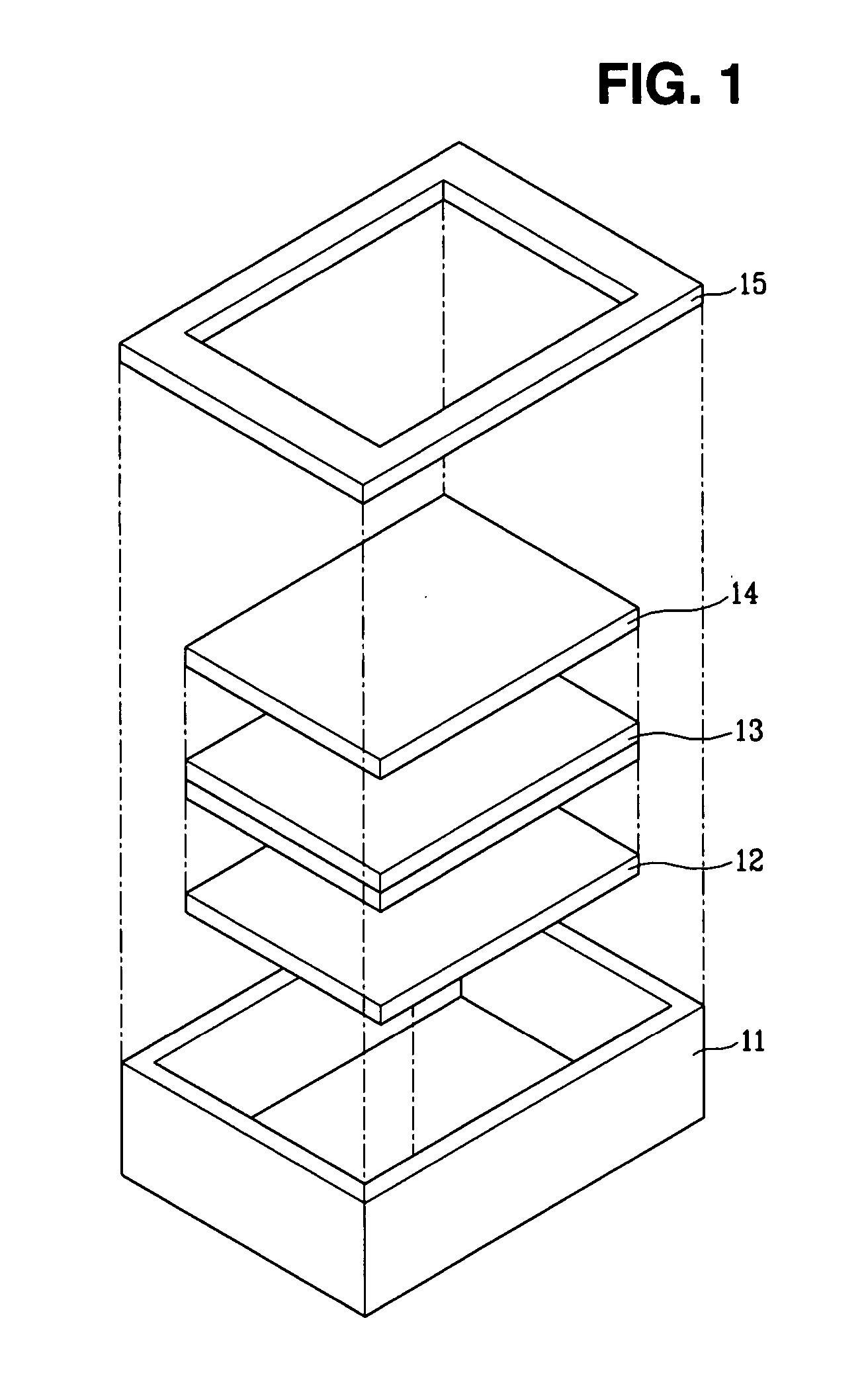
[0090] Thereafter, durability in high temperature condition was tested as described above. The results are given in Table 2 below, and the spectrum change of the adhesive film is shown in FIG. 2.

TABLE 2Transmittance in theTransmittance in the visible region (%)NIR region (%)438 nm450 nm528 nm550 nm586 nm612 nm628 nm850 nm950 nmInitial75.976.478.882.583.884.584.135.65.550068.870.579.382.383.383.683.136.25.5hourslater

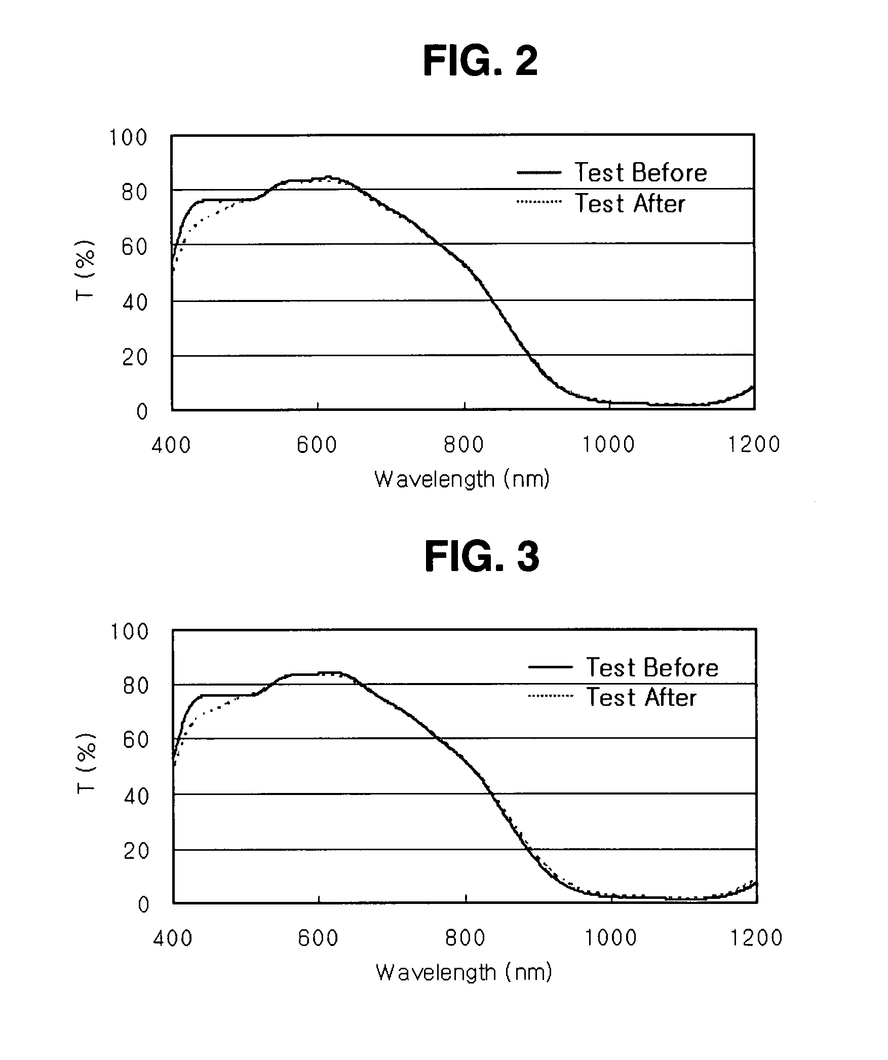
[0091] Also, the test results of high temperature and high humidity are given in Table 3, and the spectrum change of the adhesive film is shown in FIG. 3.

TABLE 3Transmittance in theTransmittance in the visible region (%)NIR region (%)438 nm450 nm528 nm550 nm586 nm612 nm628 nm850 nm950 nmInitial75.676.178.582.383.584.484.133.84.850068.870....


PUM

PropertyMeasurementUnit
Temperatureaaaaaaaaaa
Fractionaaaaaaaaaa

Abstract

The present invention relates to an adhesive film functionalizing color compensation and near infrared ray blocking and a plasma display panel filter employing the same. The present invention provides an adhesive film for a plasma display panel comprising an acryl-based adhesive and a near infrared ray absorbing dye. The present invention also provides an adhesive film for a plasma display panel comprising an acryl-based adhesive and a neon-cut dye. The adhesive film may further comprise a near infrared ray absorbing dye. The adhesive film of the present invention has superior durability at high temperature and humidity with little transmittance change and superior thermal stability. When further comprising a near infrared ray absorbing dye, it exerts both color compensation and near infrared ray blocking performances. Because the film has superior adhesivity in itself, an additional adhesive layer is unnecessary, which simplifies the manufacturing process of a plasma display panel filter and a plasma display panel.

Description

CROSS-REFERENCE TO RELATED APPLICATION [0001] This application claims priority of Korean Patent Application Nos. 10-2004-0011798 filed on Feb. 23, 2004 and 10-2005-0014754 filed on Feb. 23, 2005 in the Korean Intellectual Property Office, and U.S. patent application Ser. No. 11 / 062,927, filed on Feb. 23, 2004, the entire disclosure of which are incorporated herein by reference.BACKGROUND OF THE INVENTION [0002] (a) Field of the Invention [0003] The present invention relates to an adhesive film functionalizing such color compensation as neon-cut as well as near infrared ray blocking and a plasma display filter comprising the same, and more particularly to an adhesive film having superior durability, thermal stability, and adhesivity because of little transmittance change at high temperature and humidity and a plasma display filter using the same. [0004] (b) Description of the Related Art [0005] Recently, the plasma display panel (PDP) has been recognized as the primary flat display p...

Claims


Application Information

Patent Timeline
IPC IPC(8): B32B7/12B05D5/10G02B5/20
CPCC08K5/0091Y10T428/2891G02B5/208
Inventor CHOI, HYUN-SEOKPARK, SANG-HYUNLEE, YEON-KEUNHWANG, IN-SEOKKIM, JUNG-DOOCHO, HYUN-JULEE, DONG-WOOK
Owner LG CHEM LTD
Learn More