Fluid pressure cylinder

Active Publication Date: 2015-10-08
SMC CORP
View PDF6 Cites 4 Cited by
  • Summary
  • Abstract
  • Description
  • Claims
  • Application Information

AI Technical Summary

Benefits of technology

The present invention provides a fluid pressure cylinder that saves energy by reducing the amount of pressure fluid consumed while still allowing the piston to be highly precisely displaced with a desired thrust force. By pressing the piston through a large area, the pressure fluid can reliably displace the piston and the first rod to the other side, resulting in energy savings. Compared to a situation of supplying pressure fluid anew to the other cylinder chamber, the amount of consumed pressure fluid can be reduced, leading to additional energy savings.

Problems solved by technology

In such a situation, since the pressure of the pressure fluid when the piston is displaced toward the pressing side is governed by the discharged pressure fluid, a sufficient thrust force cannot be obtained for pushing the workpiece by the piston rod.
For this reason, with the fluid pressure cylinder, although the consumption amount of the pressure fluid can be reduced, problems occur in relation to obtaining a desired thrust force for displacing the workpiece.

Method used


Image

  • Fluid pressure cylinder
  • Fluid pressure cylinder
  • Fluid pressure cylinder

Examples


Embodiment Construction

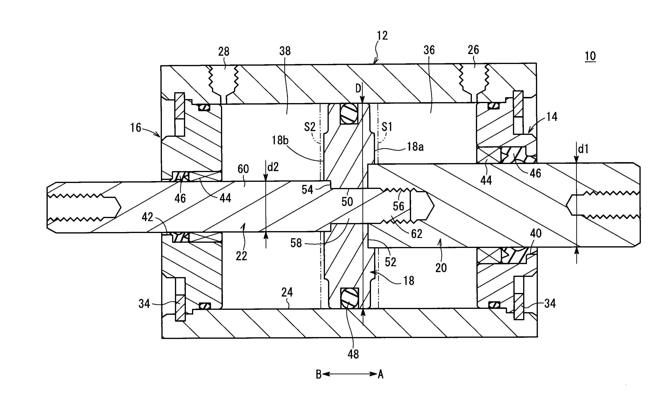
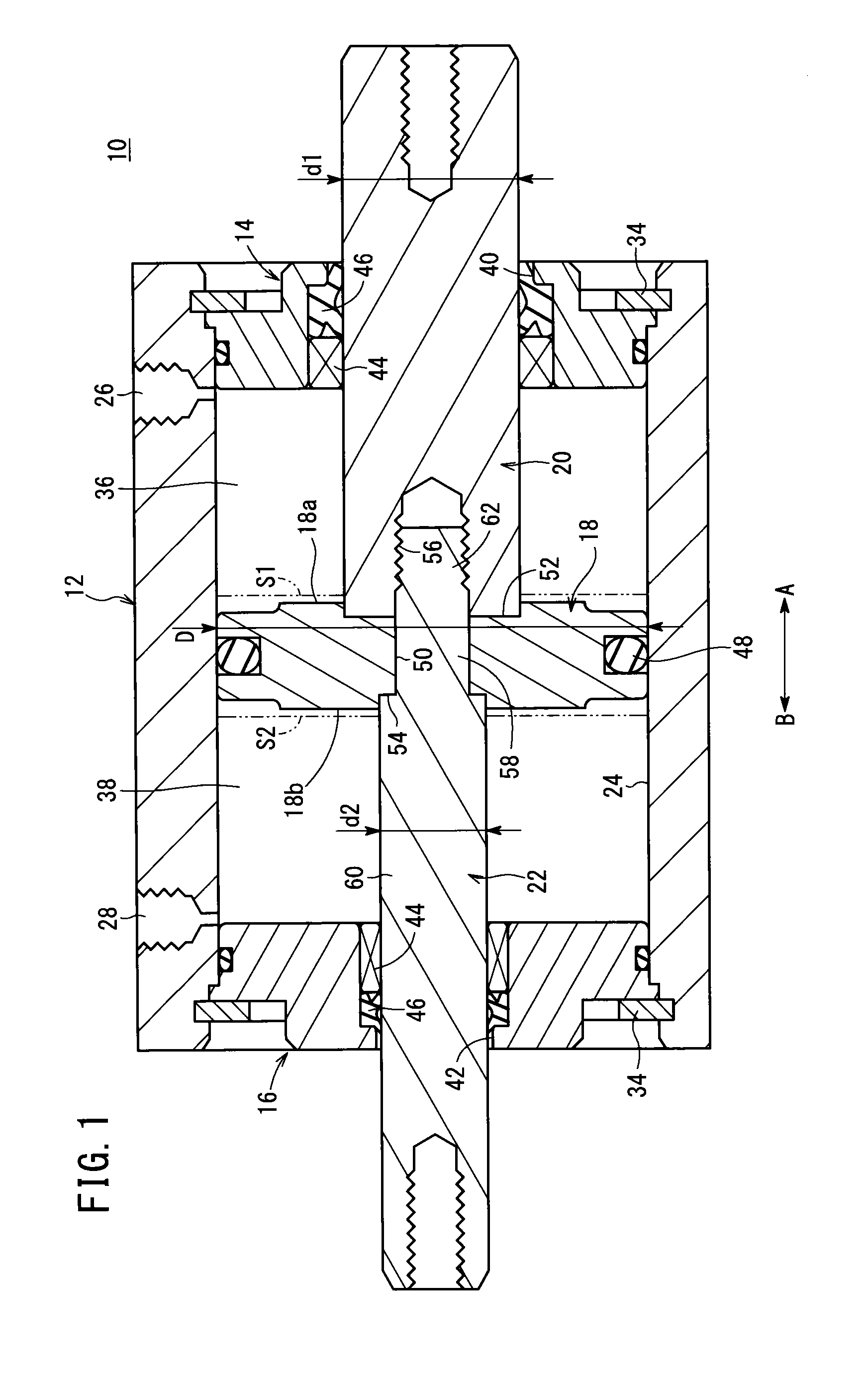
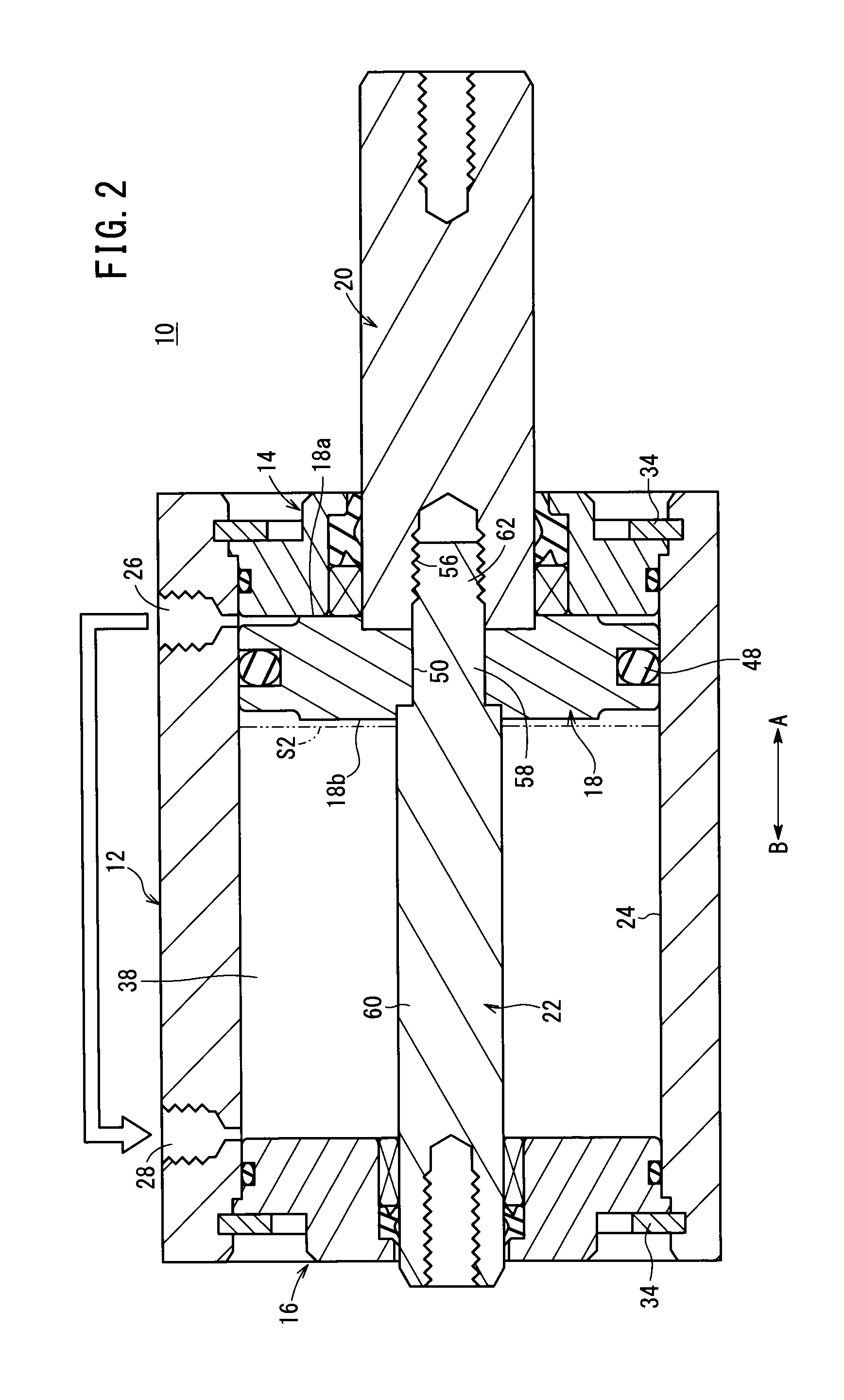
[0016]As shown in FIGS. 1 through 3, a fluid pressure cylinder 10 includes a tubular cylinder tube 12, first and second end covers 14, 16 that are mounted on opposite ends of the cylinder tube 12, a piston 18 that is disposed for displacement in the interior of the cylinder tube 12, and first and second piston rods 20, 22 that are connected to center portions of the piston 18. The fluid pressure cylinder 10 is a double rod type of fluid pressure cylinder, wherein the first and second piston rods 20, 22 are connected to respective opposite end surfaces of the piston 18.

[0017]The cylinder tube 12 is formed with a substantially rectangular shape in cross section, for example. In the interior of the cylinder tube 12, a cylinder hole 24, which is cylindrical in cross section, penetrates along the axial direction (the direction indicated by arrows A and B). The cylinder hole 24 is formed with the same cross-sectional shape along the axial direction of the cylinder tube 12.

[0018]Further, o...


PUM


Abstract

In a fluid pressure cylinder, first and second cylinder chambers facing respective opposite end surfaces of a piston are formed inside a cylinder tube including a supply port and a discharge port, and a first piston rod connected to one end surface side of the piston is formed to have a greater diameter than that of a second piston rod connected to another end surface side of the piston. Therefore, a second pressure-receiving area of a second pressure-receiving surface formed on the other end surface of the piston is greater than a first pressure-receiving area of a first pressure-receiving surface formed on the one end surface. Pressure fluid in the first cylinder chamber is supplied to the second cylinder chamber, whereby area difference between the first pressure-receiving area and the second pressure-receiving area causes the piston to move toward the first cylinder chamber.

Description

TECHNICAL FIELD[0001]The present invention relates to a fluid pressure cylinder for displacing a piston along an axial direction under the supply of a pressure fluid.BACKGROUND ART[0002]Conventionally, as a transport means for transporting workpieces or the like, a fluid pressure cylinder has been used having a piston that is displaced under the supply of a pressure fluid.[0003]With a fluid pressure cylinder of this type, recently, from the standpoint of energy conservation, a demand has arisen to reduce the amount of pressure fluid that is used. For responding to such a demand, for example, with the fluid pressure cylinder disclosed in Japanese Laid-Open Patent Publication No. 08-042511, a supply unit that supplies the pressure fluid is connected through a switching valve to two cylinder chambers. In the case that a piston is displaced in one direction, under a switching action of the switching valve, the pressure fluid is supplied at a desired pressure to one of the cylinder chamb...

Claims


Application Information

Patent Timeline
IPC IPC(8): F15B15/14
CPCF15B15/14F15B15/149F15B15/17F15B11/024F15B11/064
Inventor TAKAKUWA, YOUJI
Owner SMC CORP
Why Eureka
Try Eureka