Water Lubricated Screw Compressor
- Summary
- Abstract
- Description
- Claims
- Application Information
AI Technical Summary
Benefits of technology
Problems solved by technology
Method used
Image
Examples
first embodiment
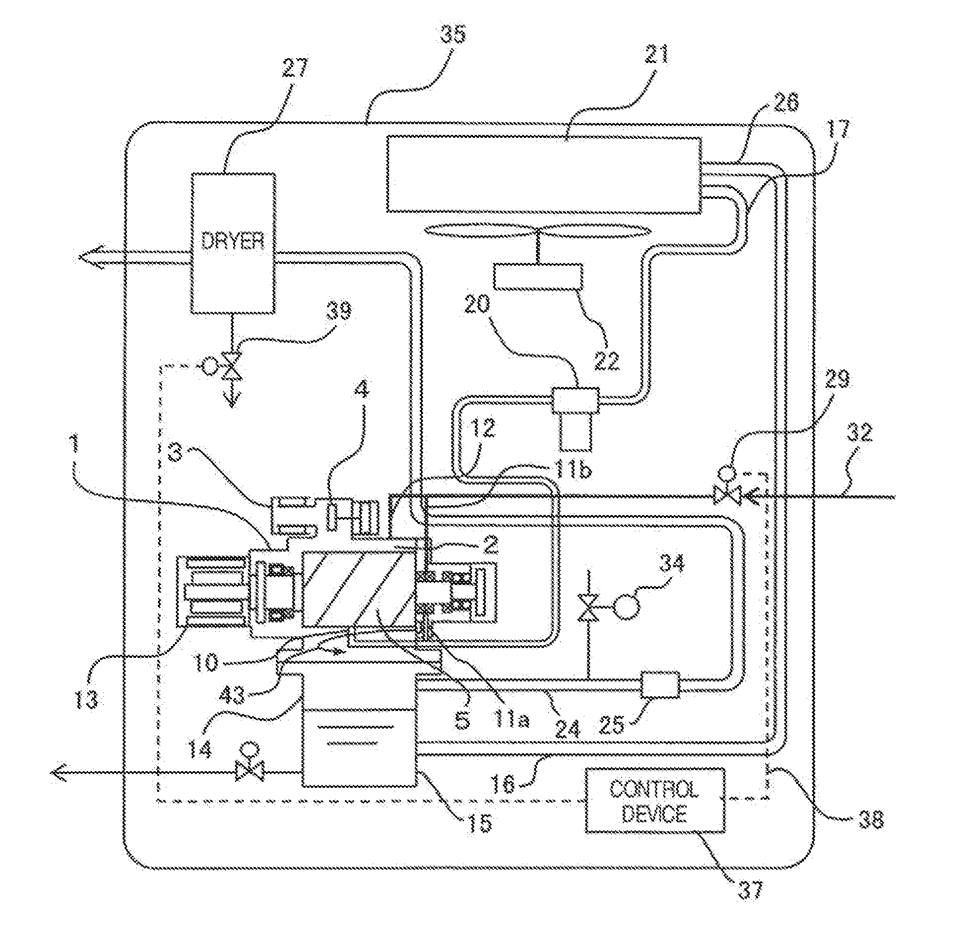
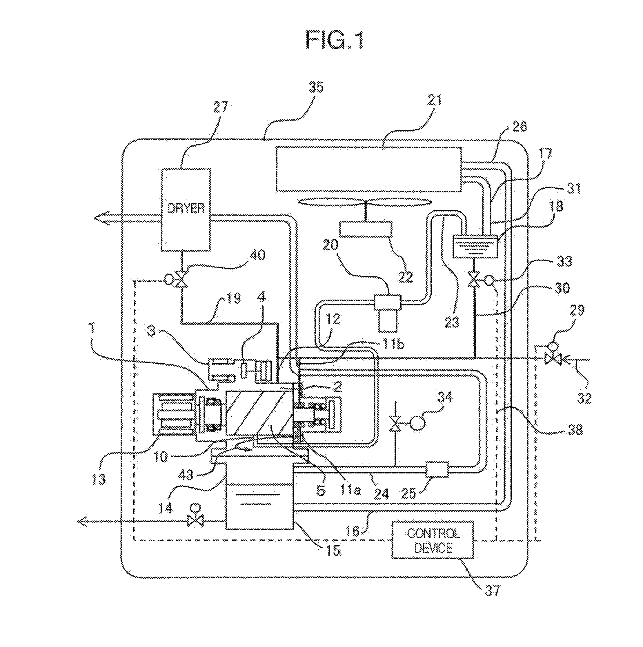
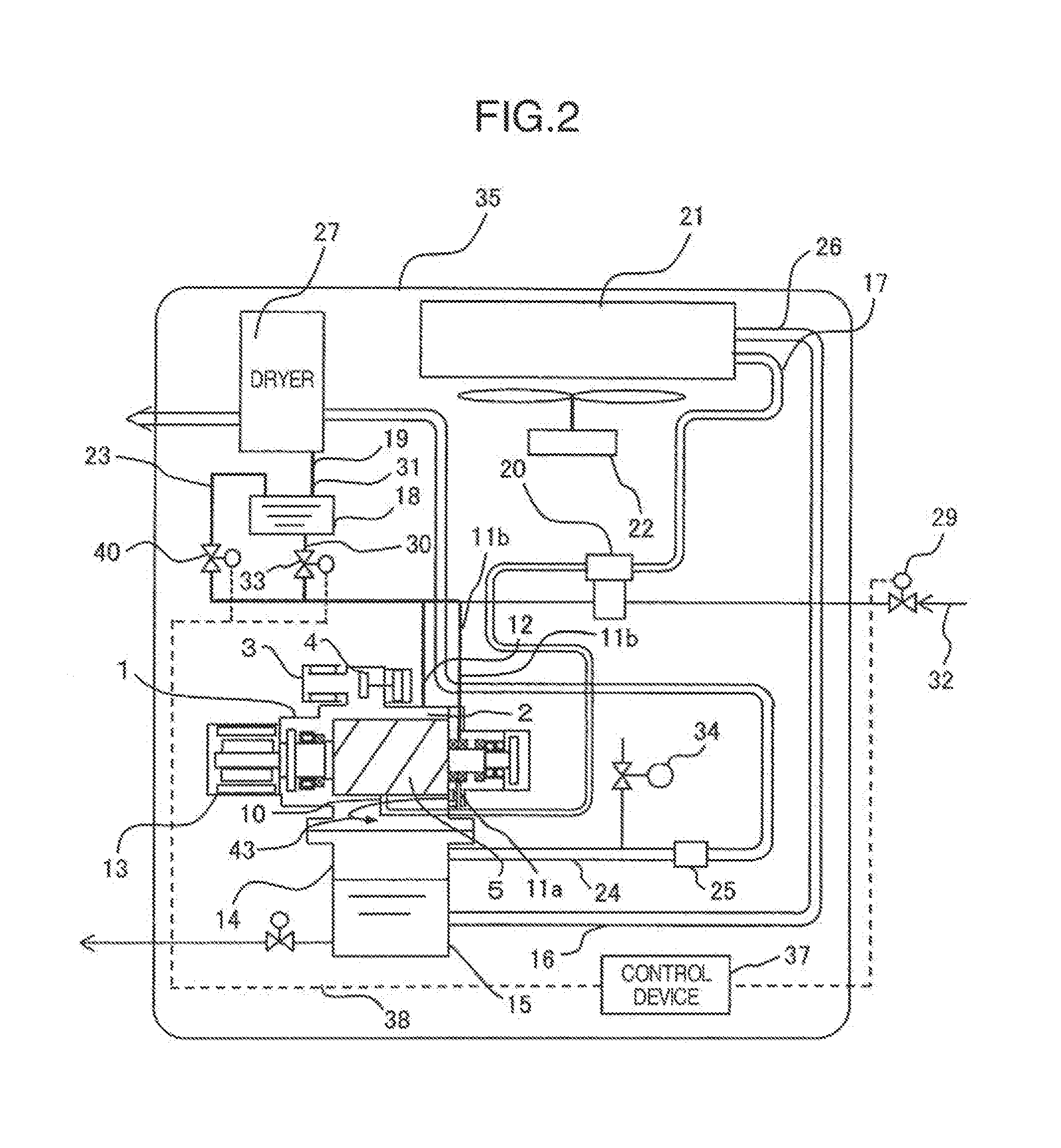
[0023]Hereinafter, the explanation will be given below concerning the present invention. FIG. 5 illustrates the structure of the water-lubricated screw compressor. In the water-lubricated screw compressor 1, a single pair of male rotor 5a and female rotor 5b are supported by cylindrical roller bearings 7 at the inlet-side axis end portion, and are supported by duplex angular bearings 6 at the discharge-side axis end portion. Moreover, the male rotor 5a and the female rotor 5b are contained inside a casing36 in a state of being engaged with each other. The lubrication of these bearings is implemented as follows: Namely, the oil filled in each of oil reservoirs provided on the inlet side and the discharge side is splashed over the bearing clearances by the rotation of splash parts 44 provided near these bearings. Furthermore, an inlet port 2 and a discharge port 45 are provided on the casing 36. Air made inlet from the inlet port 2 is filled into a compression chamber that is formed o...
third embodiment
[0046]Next, referring to FIG. 3, the explanation will be given below concerning the present invention. FIG. 3 illustrates another overflow structure for filling the water reservoir 18 with the water. The water-reservoir entrance line 31 and the water-reservoir exit line 23, which are deployed across the water-cooler exit line 17, i.e., the entrance line into the water reservoir 18, are connected to the side-surface upper portion of the water reservoir 18. The water, which flows into the water reservoir 18 from the water-reservoir entrance line 31, fills the water reservoir 18. Accordingly, the water's surface reaches the position of the water-reservoir exit line 23. Subsequently, water, whose amount is larger than the amount of the water that has flown into the water reservoir 18, flows out of the water-reservoir exit line 23. Consequently, it turns out that, at the point-in-time when the compressor is stopped, the water always fills the water reservoir 18 up to the upper surface th...
fourth embodiment
[0047]Next, referring to FIG. 4, the explanation will be given below concerning the present invention. FIG. 4 illustrates a control method of controlling the water-supply amount from the water reservoir 18. If the viscosity of the water changes depending on the start conditions or temperature, the open / close of the solenoid valve is repeated with a certain constant time-interval associated therewith without continuing to open the valve during the entire compressor's start time. This method makes it possible to control the water-supply amount. In this case, the water-supply amount becomes lowered as compared with the case where the valve is opened during the entire compressor's start time tall. In view of this situation, the diameter of the water-supply line is beforehand set at, e.g., a dimension which allows acquisition of the maximum flow amount. Then, the water-supply amount is set and given based on the ratio between the open time t1 and the close time t2 of the solenoid valve.
PUM
 Abstract
Description
Claims
Application Information
 - R&D
- Intellectual Property
- Life Sciences
- Materials
- Tech Scout
- Unparalleled Data Quality
- Higher Quality Content
- 60% Fewer Hallucinations
Browse by: Latest US Patents, China's latest patents, Technical Efficacy Thesaurus, Application Domain, Technology Topic, Popular Technical Reports.
© 2025 PatSnap. All rights reserved.Legal|Privacy policy|Modern Slavery Act Transparency Statement|Sitemap|About US| Contact US: help@patsnap.com


