Image forming apparatus, method of forming image, and computer-readable recording medium

Active Publication Date: 2012-06-28
RICOH KK
View PDF4 Cites 5 Cited by
  • Summary
  • Abstract
  • Description
  • Claims
  • Application Information

AI Technical Summary

Benefits of technology

[0009]The present invention is made in light of the above problems, and may provide an image forming apparatus capable of automatically determining an area where a transparent toner is to be applied and an amount of the transparent toner to be applied for reducing the consumed amount of the transparent toner.
[0014]According to the embodiment, an area where a transparent toner is to be applied and an amount of the transparent toner to be applied can be automatically determined to reduce the consumed amount of the transparent toner.

Problems solved by technology

However, according to the related art, for applying the transparent toner on a certain area for having the appearance of the printed document close to that of the original document, an operation of indicating the area on which the transparent toner is to be applied is necessary and it is bothersome for a user.
Further, when the transparent toner is applied on the entire surface of the paper or the entire surface of the image, a large amount of the transparent toner is necessary.

Method used


Image

  • Image forming apparatus, method of forming image, and computer-readable recording medium
  • Image forming apparatus, method of forming image, and computer-readable recording medium
  • Image forming apparatus, method of forming image, and computer-readable recording medium

Examples


first embodiment

[0034]Next, the first embodiment will be described below with reference to drawings.

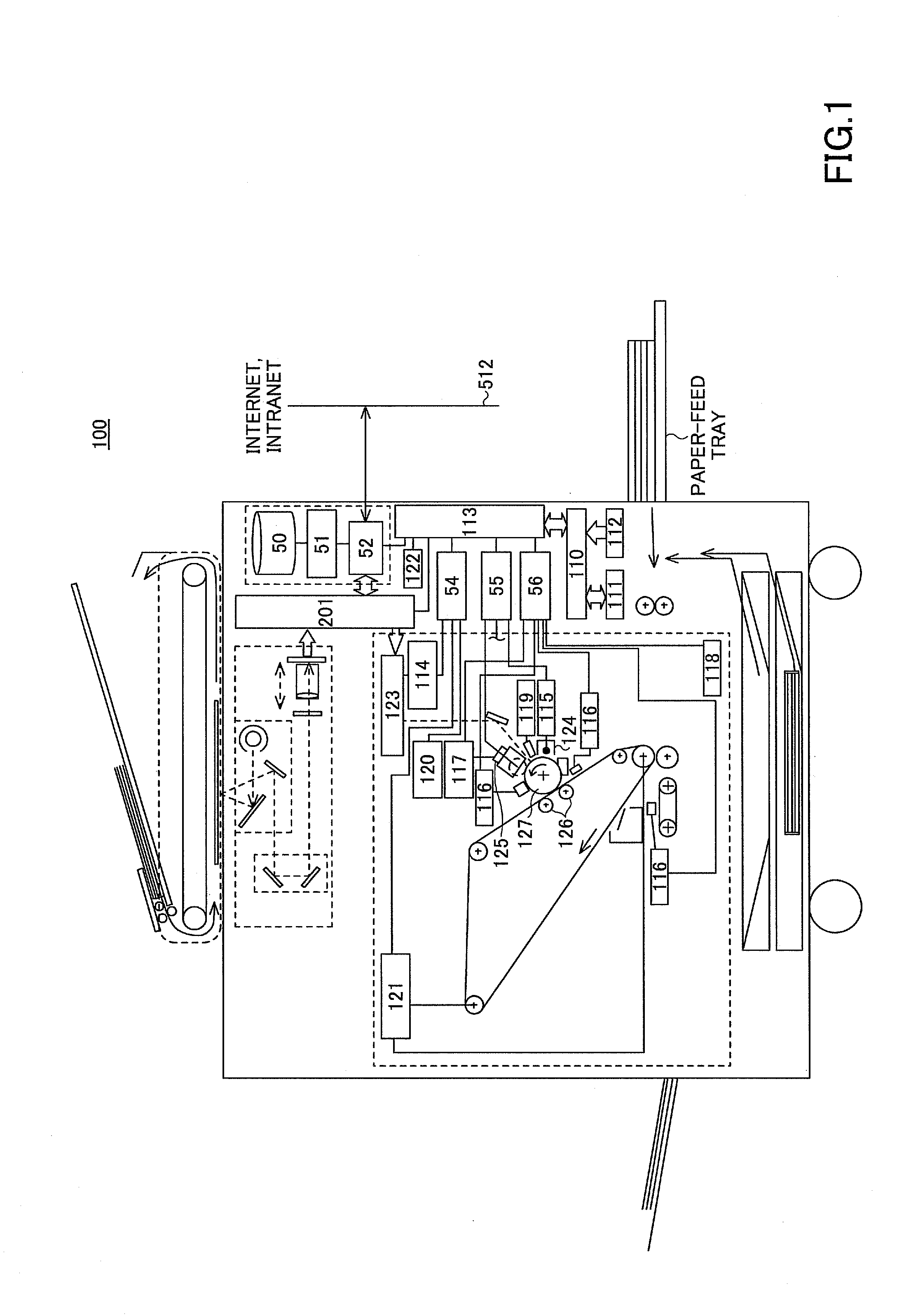
[0035]FIG. 1 is an explanatory view for explaining the structure of an image forming apparatus 100 of the first embodiment.

[0036]The image forming apparatus 100 of the present embodiment includes a main control unit (CPU, Central Processing Unit) 110, a RAM (Random Access Memory) 111, a ROM (Read Only Memory) 112, an interface I / O 113, a laser optical control unit 114, power circuits 115, optical sensors 116, a toner concentration sensor 117, an environment sensor 118, photosensitive surface potential sensors 119 (only one of which is shown in the drawings), a toner supply circuit 120, an intermediate transfer belt driver 121, an operations unit 122, a laser optical scanning system 123, charging devices 124 (only one of which is shown in the drawings), developing devices 125 (only one of which is shown in the drawings), bias rollers 126 (only one set of which is shown in the drawings), and photosensi...

second embodiment

[0124]Next, the second embodiment will be described below with reference to drawings. Only the method of determining the dispersion of the read value is different from that of the first embodiment. In the following embodiment, only the part different from the first embodiment will be explained.

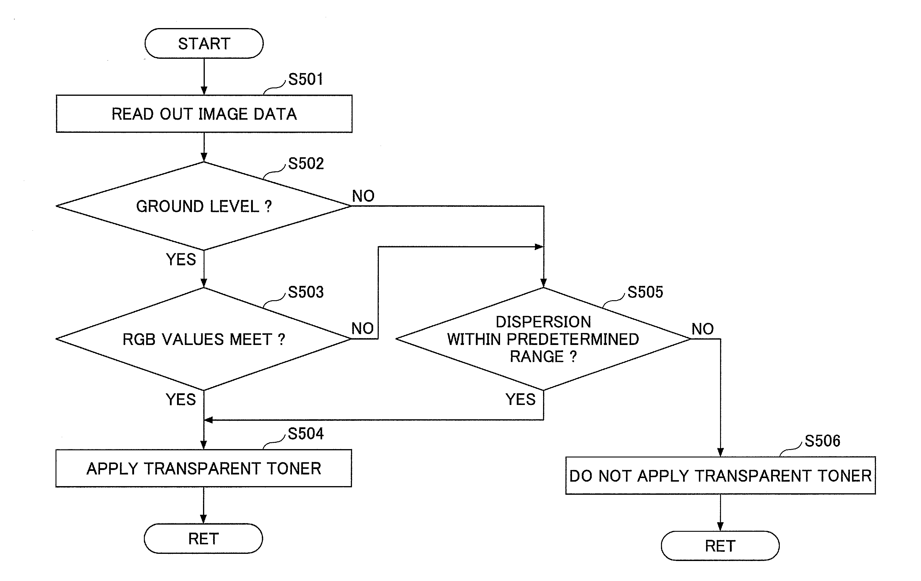
[0125]FIG. 10 is a flowchart for explaining operations for determining a dispersion of the read values of the second embodiment. The processes of FIG. 10 correspond to the process of step S505 of FIG. 5.

[0126]In this embodiment, after the image data is read, the dispersion of the image data is determined based on a peak value of the frequency with respect to the read value, a width of the peak, a number of peaks or the like of the image data within a predetermined area formed by a predetermined number of pixels.

[0127]In this embodiment, the gloss applying unit 304 forms histograms of the pixels whose read values are more than or equal to a predetermined value (bright pixels) within the predete...

third embodiment

[0138]Next, the third embodiment will be described below with reference to drawings. Only the method of determining the dispersion of the read value where a dot (halftone dot) is detected in the third embodiment is different from that of the first embodiment. In the following embodiment, only the part different from the first embodiment will be explained.

[0139]FIG. 12 is a flowchart for explaining operations for determining a dispersion of the read values of the third embodiment.

[0140]In this embodiment, the area separation unit 303 detects whether the target pixel is a dot. When the target pixel is not the dot in step S1201 (No in step S1202), the gloss applying unit 304 performs the processes of FIG. 6 (step S1203). When the target pixel is detected to be the dot in step S1202 (Yes in step S1202), the gloss applying unit 304 detects a frequency component of the dot (step S1204). Subsequently, the gloss applying unit 304 removes the frequency component of the dot of the pixel which...


PUM


Abstract

Disclosed is an image forming apparatus capable of forming an image with a colored toner and a transparent toner based on image data of a read document, including a dispersion calculation unit that calculates a dispersion of a target pixel and a group of pixels including the target pixel and peripheral pixels of the target pixel; an applying area determining unit that determines whether to apply the transparent toner on the target pixel based on the dispersion of the target pixel; and an amount determining unit that determines an amount of the transparent toner to be applied on the target pixel for which the transparent toner is determined to be applied based on the dispersion of the target pixel.

Description

BACKGROUND OF THE INVENTION[0001]1. Field of the Invention[0002]The present invention relates to an image forming apparatus, a method of forming an image, and a computer-readable recording medium and more specifically, to an image forming apparatus, a method of forming an image, and a computer-readable recording medium having recorded thereon a program that causes a computer to execute a method of forming an image where an image is formed with a colored toner and a transparent toner based on image data of a read document.[0003]2. Description of the Related Art[0004]An image forming apparatus capable of applying a transparent toner (an achromatic toner, a clear toner) based on gloss of a document or a kind of printing paper is known. As for such an image forming apparatus, when the transparent toner is applied, the transparent toner is coated on an entire surface of the paper, the transparent toner is coated on an entire surface of the image after detecting the image, the transparent...

Claims


Application Information

Patent Timeline
IPC IPC(8): H04N1/60
CPCG03G15/5025H04N1/54G03G15/6585
Inventor HAYASHI, KOJI
Owner RICOH KK
Why Eureka
Try Eureka