Projection device

Inactive Publication Date: 2015-10-08
GOOGLE LLC
View PDF4 Cites 10 Cited by
  • Summary
  • Abstract
  • Description
  • Claims
  • Application Information

AI Technical Summary

Benefits of technology

[0059]The distance between the first lens of the lens pair and the collimation lens do not influence the functionalit

Problems solved by technology

However, circular pixels are difficult to achieve since the projected light source diverges; in particular,

Method used


Image

  • Projection device
  • Projection device
  • Projection device

Examples


first embodiment

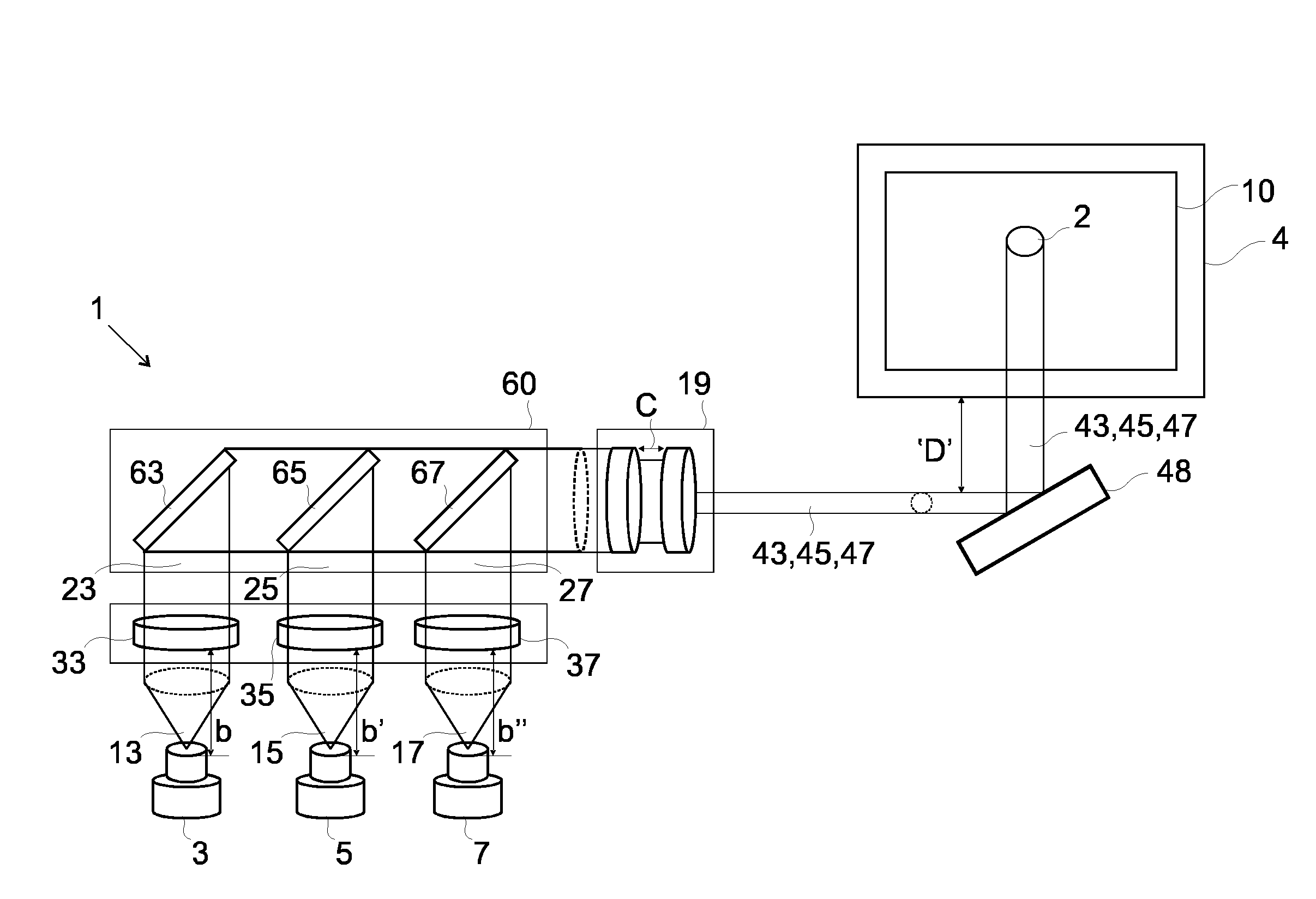
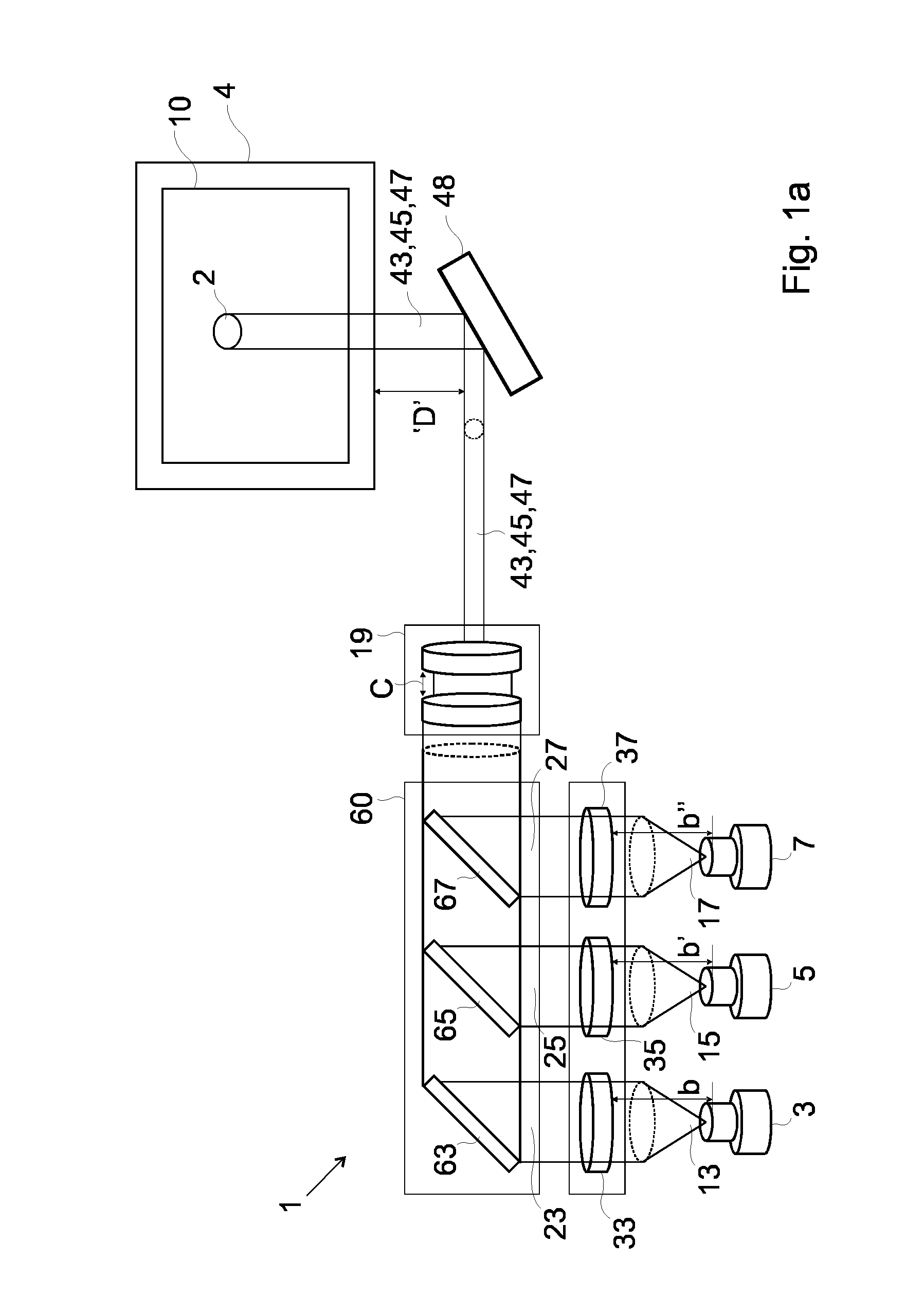
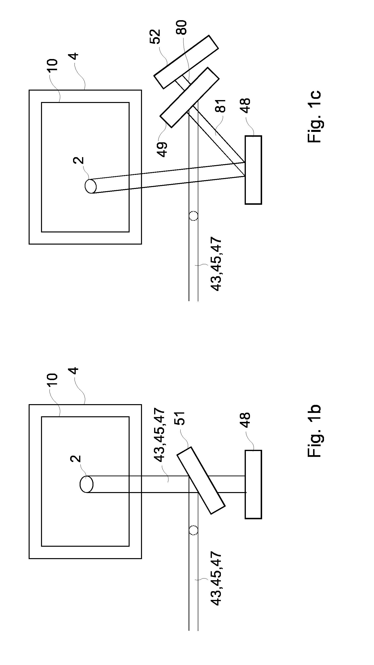
[0097]FIG. 1a provides a perspective view of a projection device 1 according to the present invention. The projection device 1 is shown to project a pixel 2 onto a display screen 4 which is positioned a predefined distance ‘D’ away from the projection device 1. The pixel 2 defines part of a 2-D image 10 which is projected by the projection device 1 onto the display screen 4.

[0098]The projection device 1 comprises, a red light source 3, a green light source 5, and a blue light source 7 which can emit red, green and blue light 13,15,17 respectively.

[0099]The projection device 1 comprises a means for collimating 9 the light emitted from the red, green and blue light sources 3,5,7 to provide red, green and blue collimated light beams 23,25,27. The means for collimating 9 comprises three collimating lenses 33,35,37 each of which is arranged in optical communication with a respective light source 3,5,7.

[0100]An optical modifier means 19, is arranged to be in optical communication with the...

second embodiment

[0108]FIG. 2 provides a perspective view of a projection device 200 according to the present invention. The projection device 200 comprises many of the same features of the projection device 1 shown in FIG. 1 and like features are awarded the same reference numerals.

[0109]The projection device comprises beam combiner 201 in the form of a prism element 201 which is arranged to deflect and combine the red, green and blue collimated light beams 23,25,27 which it receives from the three collimating lenses 33,35,37, to the optical modifier means 19.

third embodiment

[0110]FIG. 3 provides a perspective view of a projection device 300 according to the present invention; The projection device 300 comprises many of the same features of the projection device 1 shown in FIG. 1 and like features are awarded the same reference numerals. In the projection device 300 the means for collimating 9 is in direct optical communication with the optical modifier means 19.

[0111]The projection device 300 comprises a beam combiner 60 as used in the embodiment shown in FIG. 1. The beam combiner 60 comprises deflectors 63, 65 and 67 are provided to direct the light beam to the MEMS mirror 48 and to combine the red, green and blue projection beams 43,45,47; alternatively the beam combiner could be defined by a prism component 201 as used in the embodiment shown in FIG. 2.

[0112]In the projection device 300 optical modifier means 19 comprises three pairs of lens 301,303,305, wherein each lens pair 301,303,305, is configured to be in optical communication with one of the...


PUM

PropertyMeasurementUnit
Shapeaaaaaaaaaa

Abstract

A projection device comprising, a red light source, a green light source, and a blue light source which can emit red, green and blue light respectively, a beam combiner which is configured such that it can combine light beams; a means for collimating the light emitted from the red, green and blue light sources to provide red, green and blue collimated light beams, an optical modifier means, which is arranged such that the optical modifier means can receive the red, green and blue collimated light beams, and wherein the optical modifier means is configured to modify cross sectional dimensions of the red, green and blue collimated light beams to provide red, green and blue projection beams each of which has a circular cross section, and wherein the optical modifier means is configured, and the distances between the light sources and means for collimating are set, such that the dimensions of the circular cross sections of the red, green and blue projection beams are equal at a predetermined distance from the projection device such that the spot sizes of each of the red, green and blue projection beams are equal or have predefined sport sizes at the predetermined distance from the projection device; MEMS mirror which is configured such that it can oscillate about at least one oscillation axis to scan the red, green and blue projection beams across a projection screen which is positioned at the predetermined distance from the projection device.

Description

FIELD OF THE INVENTION[0001]The present invention concerns a projection device which can project circular pixels onto a display screen. In particular, but not exclusively, the present invention concerns a projection device which is configured to project red, green and blue projection beams each of which have circular cross sections, wherein the circular cross section of each projection beam is dimensioned such that, at a predetermined distance from the projection device the circular cross sections of the projection beams are equal, so that the spot size of each of the projection beams is equal at the predetermined distance from the projection device, thereby enabling a circular pixel may be projected onto a display screen which is positioned at the predetermined distance from the projection device.BACKGROUND TO THE INVENTION[0002]A MEMS micro-mirror device is a device that contains an optical MEMS (Micro-Electrical-Mechanical-System). The optical MEMS may comprise a cylindrical, rec...

Claims


Application Information

Patent Timeline
IPC IPC(8): G03B21/20G03B21/28G03B21/14
CPCG03B21/208G03B21/147Y10T29/49117G03B21/28G03B21/145G03B21/2066G02B26/0833G02B27/104
Inventor KILCHER, LUCIOABELE, NICOLAS
Owner GOOGLE LLC
Why Eureka
Try Eureka