Optical imaging lens

a technology of optical imaging and lens, applied in the field of optical imaging lenses, can solve the problems of difficult reduction of the length of the telephoto lens, the design of the optical imaging lens cannot produce an optical imaging lens having both imaging quality and small size, and the need for good optical performan

Active Publication Date: 2018-02-20
GENIUS ELECTRONICS OPTICAL XIAMEN
View PDF1 Cites 5 Cited by
  • Summary
  • Abstract
  • Description
  • Claims
  • Application Information

AI Technical Summary

Benefits of technology

[0008]The invention provides an optical imaging lens capable of maintaining good optical performance under the condition of a reduced lens depth.

Problems solved by technology

However, to prevent reduction in photographic effects and quality, when the length of the optical imaging lens is reduced, good optical performance still needs to be achieved.
However, the optical imaging lens design cannot produce an optical imaging lens having both imaging quality and small size simply by reducing the ratio of, for instance, a lens having good imaging quality, and the design process involves material properties, and actual issues on the production line such as assembly yield also needs to be considered.
As a result, the length of a telephoto lens is hard to reduce.
The dilemma of reducing lens length or increasing the magnification and maintaining the imaging quality cause the design of the optical imaging lens to be hard.

Method used


Image

  • Optical imaging lens
  • Optical imaging lens
  • Optical imaging lens

Examples


first embodiment

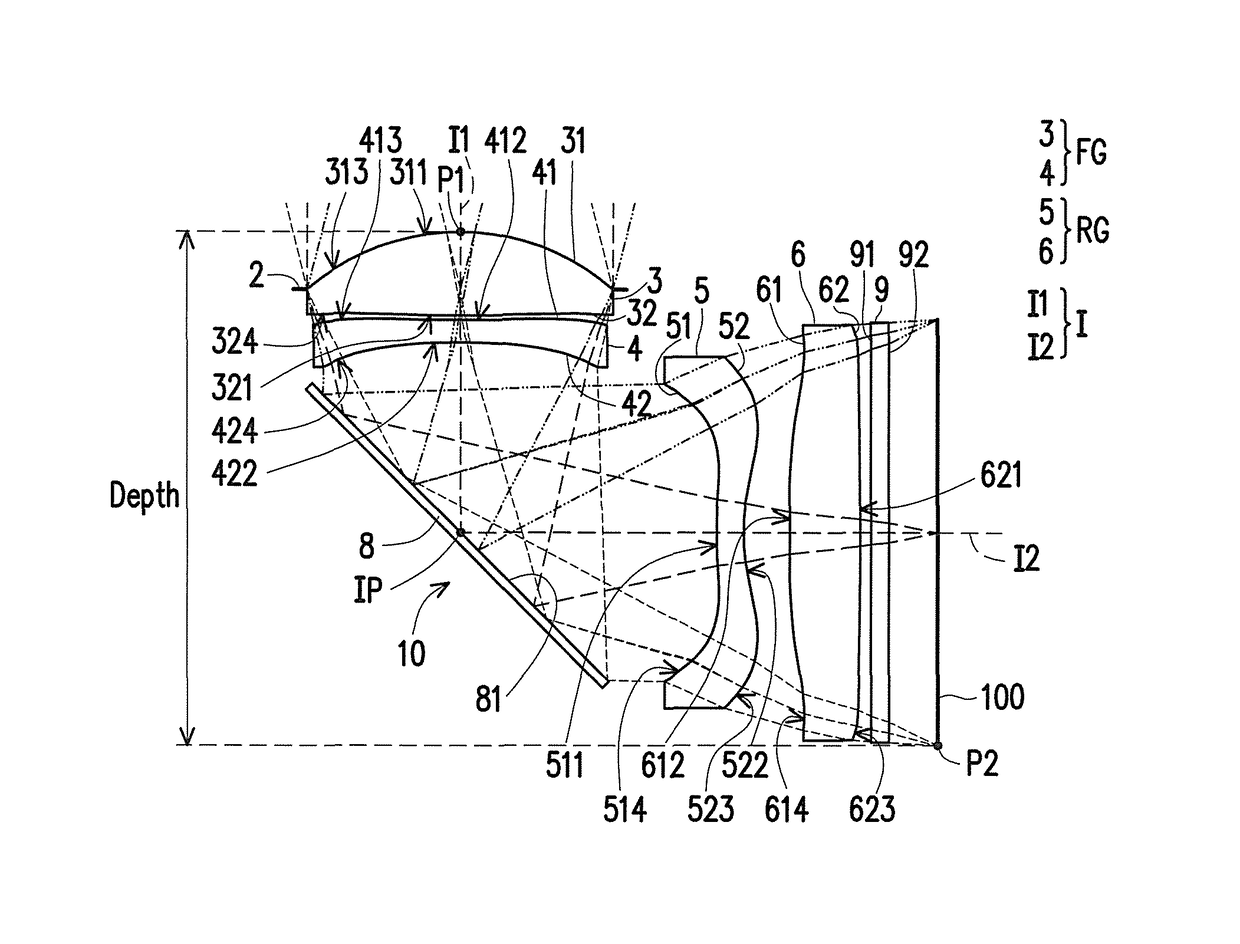
[0080]Moreover, the relationship between each of the important parameters in the optical imaging lens 10 of the first embodiment is as shown in FIG. 38.[0081]wherein,[0082]T1 is the thickness of the first lens element 3 on the optical axis I, i.e., on the first optical axis I1;[0083]T2 is the thickness of the second lens element 4 on the optical axis I, i.e., on the first optical axis I1;[0084]T3 is the thickness of the third lens element 5 on the optical axis I, i.e., on the second optical axis I2;[0085]T4 is the thickness of the fourth lens element 6 on the optical axis I, i.e., on the second optical axis I2;[0086]TF is the thickness of the filter 9 on the optical axis I, i.e., on the second optical axis I2;[0087]G12 is the distance from the image-side surface 32 of the first lens element 3 to the object-side surface 41 of the second lens element 4 on the optical axis I, i.e. an air gap from the first lens element 3 to the second lens element 4 on the first optical axis I1;[0088]G...

second embodiment

[0118]The detailed optical data of the optical imaging lens 10 is as shown in FIG. 12, and in the second embodiment, the EFL of the optical imaging lens 10 is 10.025 mm, the HFOV thereof is 14.069°, the Fno thereof is 2.800, the TTL thereof is 9.285 mm, the ImaH thereof is 2.517 mm, the fFG thereof is 8.456 mm, and the Depth thereof is 6.043 mm.

[0119]FIG. 13 shows each of the aspheric coefficients of the object-side surfaces 31, 41, 51, and 61 and the image-side surfaces 32, 42, 52, and 62 of the second embodiment in general formula (1).

[0120]Moreover, the relationship between each of the important parameters in the optical imaging lens 10 of the second embodiment is as shown in FIG. 38.

[0121]In the longitudinal spherical aberration figure of FIG. 11A of the second embodiment in the condition that the pupil radius thereof is 1.8000 mm, the imaging point deviation of off-axis rays at different heights is controlled to be within the range of ±40 microns. In the two field curvature fig...

third embodiment

[0124]The detailed optical data of the optical imaging lens 10 is as shown in FIG. 16, and in the third embodiment, the EFL of the optical imaging lens 10 is 10.079 mm, the HFOV thereof is 14.008°, the Fno thereof is 2.801, the TTL thereof is 9.434 mm, the ImaH thereof is 2.517 mm, the fFG thereof is 8.51 mm, and the Depth thereof is 5.920 mm.

[0125]FIG. 17 shows each of the aspheric coefficients of the object-side surfaces 31, 41, 51, and 61 and the image-side surfaces 32, 42, 52, and 62 of the third embodiment in general formula (1).

[0126]Moreover, the relationship between each of the important parameters in the optical imaging lens 10 of the third embodiment is as shown in FIG. 38.

[0127]In the longitudinal spherical aberration figure of FIG. 15A of the third embodiment in the condition that the pupil radius thereof is 1.8000 mm, the imaging point deviation of off-axis rays at different heights is controlled to be within the range of ±37 microns. In the two field curvature figures ...


PUM


Abstract

An optical imaging lens includes a first lens element, a second lens element, a third lens element, and a fourth lens element from an object side to an image side in order along an optical axis. The first lens element to the fourth lens element each include an object-side surface and an image-side surface. The first lens element has positive refracting power. The second lens element has negative refracting power. At least one of the object-side surface and the image-side surface of the third lens element is an aspheric surface. At least one of the object-side surface and the image-side surface of the fourth lens element is an aspheric surface. A maximum distance between the image-side surface of the first lens element and the object-side surface of the second lens element in a direction parallel to the optical axis is less than 0.2 mm.

Description

CROSS-REFERENCE TO RELATED APPLICATION[0001]This application claims the priority benefit of China application serial no. 201610725556.6, filed on Aug. 25, 2016. The entirety of the above-mentioned patent application is hereby incorporated by reference herein and made a part of this specification.BACKGROUND OF THE INVENTIONField of the Invention[0002]The invention relates to an optical imaging lens.Description of Related Art[0003]In recent years, the popularity of mobile products such as mobile phones and digital cameras allowed the rigorous development of imaging module-related techniques, and the imaging module mainly contains elements such as an optical imaging lens, a module holder unit, and a sensor, and the thin and light developing trend of mobile phones and digital cameras also resulted in a greater demand of the compactness of the imaging module. With the advancement of the techniques of charge-coupled device (CCD) and complementary metal oxide semiconductor (CMOS) and reduc...

Claims


Application Information

Patent Timeline
Patent Type & Authority Patents(United States)
IPC IPC(8): G02B17/00G02B13/00G02B9/34G02B27/00
CPCG02B13/004G02B9/34G02B13/0065G02B27/0025G02B13/18G02B13/02
Inventor BONE, MATTHEWLIN, MAOZONGXIE, ZHENFENG
Owner GENIUS ELECTRONICS OPTICAL XIAMEN
Why Eureka
Try Eureka