

Relay System and Switching Device
- Summary
- Abstract
- Description
- Claims
- Application Information
AI Technical Summary
Benefits of technology
Problems solved by technology
Method used
Image

Examples
first embodiment
General Configuration of Relay System
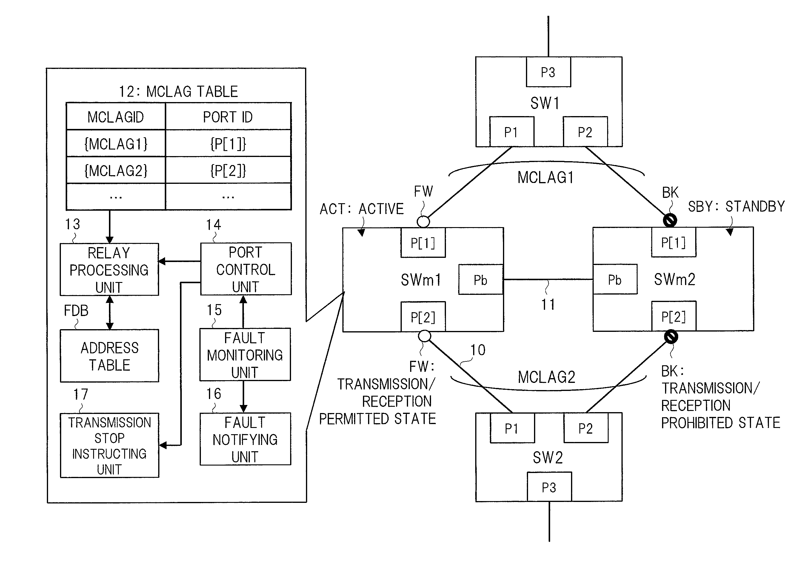
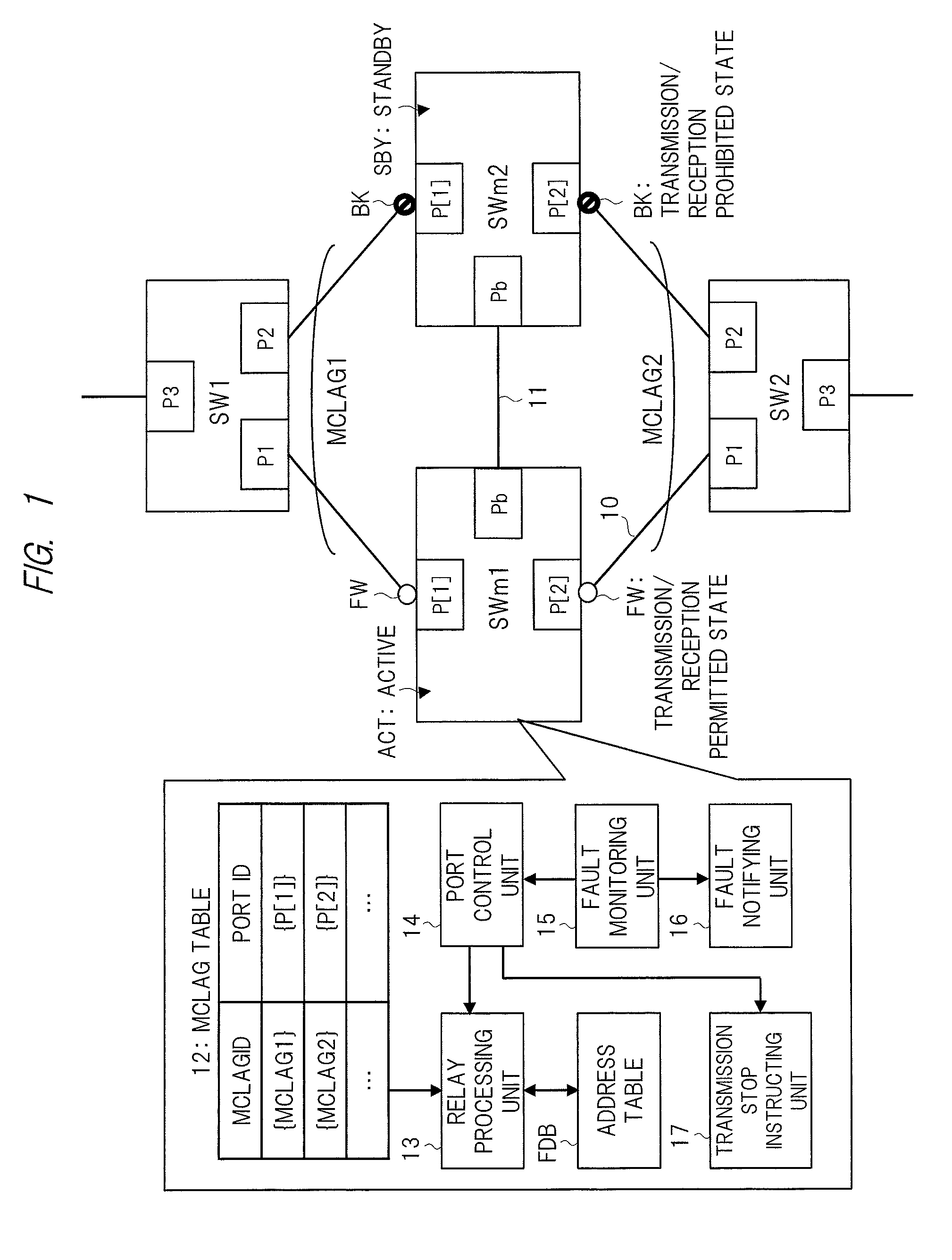
[0036]FIG. 1 is a schematic diagram of a configuration example of a relay system according to the first embodiment of the present invention. The relay system of FIG. 1 includes two L2 switching devices (first and second switching devices) SWm1 and SWm2 to which an inter-device LAG is applied and a plurality of (here, two) user L2 switching devices SW1 and SW2.
[0037]Each of the L2 switching devices SWm1 and SWm2 has a MCLAG port group (first port group) P[1], a MCLAG port group (second port group) P[2], and a bridge port Pb. The MCLAG port group P[1] is made up of one or a plurality of MCLAG ports (first ports), and the MCLAG port group P[2] is made up of one or a plurality of MCLAG ports (second ports). In the first embodiment, each of the MCLAG port groups P[1] and P[2] is made up of one MCLAG port. Therefore, in the first embodiment, each of P[1] and P[2] represents both of the MCLAG port group and the MCLAG port.
[0038]The L2 switching device (...
second embodiment
General Configuration of Relay System
Application Example [1]
[0140]FIG. 12 is a schematic diagram of a configuration example and apart of operation example of a relay system according to the second embodiment of the present invention. The relay system of FIG. 12 is different from the relay system of FIG. 1 in that each of the MCLAG port groups P[1] and P[2] of the MCLAG device is made up of n (n=2 in this case) MCLAG ports and the bridge port Pb is also made up of a plurality of (two in this case) bridge ports. Consequently, switching devices are connected via a plurality of communication lines 10. As a typical example thereof, in FIG. 12, the MCLAG port group (first port group) P[1] is made up of two MCLAG ports (first ports) P[1,1] and P[1,2], and the two MCLAG ports P[1,1] and P[1,2] are connected to the L2 switching device SW1 via the communication lines 10, respectively.
[0141]Also, FIG. 12 shows a simplified configuration example of the user L2 switching devices SW1 and SW2. The...
third embodiment
General Configuration of Switching Device
PUM
 Abstract
Description
Claims
Application Information