Interior paneling part comprising a planar heating element and method for the production thereof

a technology of interior paneling and heating elements, which is applied in the direction of vehicle heating/cooling devices, transportation and packaging, and other domestic articles, can solve the problems of insufficient embedding of heating elements in foam bodies, inability to meet the needs of interior paneling, etc., to achieve the effect of easy and convenient shaping, avoiding inhomogeneity in composites, and reducing or avoiding inhomogeneity

Active Publication Date: 2015-10-15
LISA DRAXLMAIER GMBH
View PDF4 Cites 1 Cited by
  • Summary
  • Abstract
  • Description
  • Claims
  • Application Information

AI Technical Summary

Benefits of technology

[0012]It is an object of the present disclosure to provide a method for producing an interior trim part including an inserted planar heating element, which allows easy and at the same time precise positioning of the planar heating element with respect to the dimensions of the interior trim part. Moreover, inhomogeneities in the composite are to be reduced or avoided. It is a further object of the present disclosure to provide a corresponding interior trim part, in which the planar heating element can be precisely positioned and which can be shaped easily and with high quality in complex geometries.

Problems solved by technology

However, in this process, the positioning of the heating element in the cavity of the mold poses a problem.
Inadequate positioning of the planar heating element in the z-direction can cause the same to be disposed undesirably close to one of the planar outer sides of the foam body or of the interior trim part.
Insufficient embedding of the heating element in the foam body can also be disadvantageous on the other outer side, i.e., the outer side of the interior trim part located opposite the visible side.
This not only generates heat losses, but also increases the likelihood that the planar heating element or the carrier element is damaged during installation or during operation.
During production using a mold, the positioning in the z-direction poses a problem.
This has the disadvantage that the adhesive bonding of the cut foam constitutes an additional work step, which considerably increases the production time.
In addition, this drastically limits the freedom of design of such an interior trim part comprising a planar heating element.
For example, the cut foam is frequently cut from a block and therefore has undesirable corners.
This has the disadvantage that additional work steps are necessary for placing the spacers.
In addition, the spacers create the risk of the contours thereof being apparent on the surface of the finished interior trim part.
Because these spacers as such are usually made of a foam material, they can deform when the foam material is added, which in turn results in imprecise positioning of the planar heating element.
Such contact not only can result in heat losses, but also can damage the carrier elements or the heating element.
These shapes may provide good support of the planar heating element, while on the other hand the round shape of the protrusions impairs the flow of the foam material in the mold cavity as little as possible.

Method used


Image

  • Interior paneling part comprising a planar heating element and method for the production thereof
  • Interior paneling part comprising a planar heating element and method for the production thereof
  • Interior paneling part comprising a planar heating element and method for the production thereof

Examples


Embodiment Construction

[0056]Unless indicated otherwise, identical or functionally equivalent components are denoted by the same reference numerals in the figures. Further modifications mentioned in this context can be combined with each other to form new embodiments.

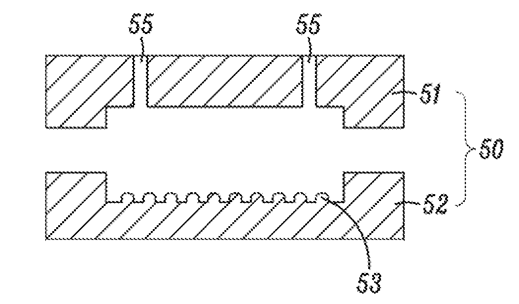
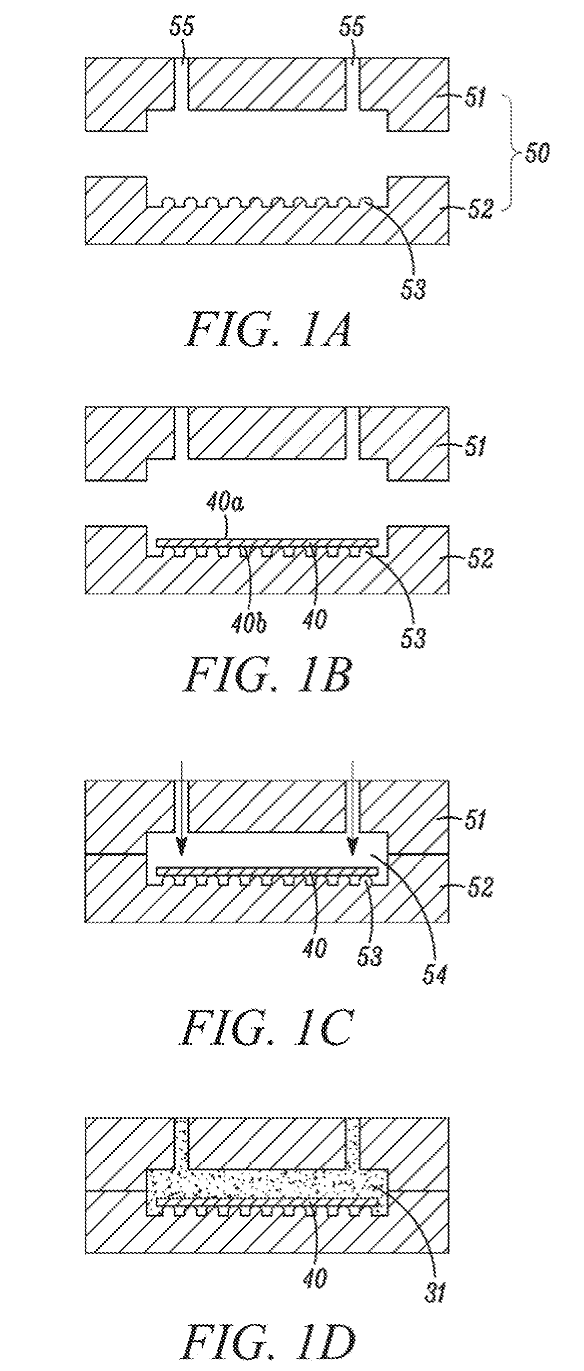
[0057]FIGS. 1A to 1D show sectional views of a mold tool 50, which is used to implement the methods according to the present disclosure for producing an interior trim part 1. More specifically, FIGS. 1A to 1D each show a stage of the production method.

[0058]As is shown in FIG. 1A, a suitable mold tool 50 has two mold halves 51 and 52. Each of these can have a cutout, which together define a mold cavity 54. The mold tool 50 further has feeds 55 via which a foam material 31 can be introduced into the mold cavity 54. The division of the mold tool 50 into two mold halves 51 and 52 shall only be understood as an example here. The shown embodiment of the mold cavity 54 is also only provided to better illustrate the basic idea of the disclosure.

[005...


PUM

PropertyMeasurementUnit
diameteraaaaaaaaaa
distanceaaaaaaaaaa
diameteraaaaaaaaaa

Abstract

In accordance with the present disclosure, there is provided a method for producing an interior trim part. The method includes introducing a planar heating element into a cavity of a mold tool. The planar heating element has a first planar side facing away from a visible side of the interior trim part and a second planar side opposite to the first planar side, the mold tool has a plurality of protrusions protruding into the cavity, and the first planar side is seated on at least a portion of the plurality of protrusions. The method further includes adding a foam material into the cavity to cover the planar heating element, such that a foam layer is formed on both the first and second planar sides.

Description

CROSS-REFERENCE TO RELATED APPLICATION[0001]This application is based upon and claims the benefit of prior German Application No. 10 2014 005 190.0, filed on Apr. 9, 2014, the entire contents of which are incorporated herein by reference.FIELD OF THE INVENTION[0002]The present disclosure relates to a method for producing interior trim parts, in particular for vehicles (such as motor vehicles, trains, airplanes, or boats), and to such an interior trim part. The disclosure relates in particular to interior trim parts comprising a planar heating element, which is embedded into a foam body of the interior trim part.BACKGROUND OF THE DISCLOSURE[0003]Interior trim parts that are used increasingly in vehicles are provided with planar heating elements. This applies not only to seat cushions, but to an increasing extent also to other trim parts, such as center arm rests or door or side trims. So as to preserve a pleasant feel of the interior trim parts and keep the heating element away from ...

Claims


Application Information

Patent Timeline
Patent Type & Authority Applications(United States)
IPC IPC(8): B60H1/00B60H1/22B60R13/02B29C70/88B29C70/68
CPCB60H1/00271B29C70/88B29L2031/3041B60R13/02B60H1/2215B29C70/682B29C44/1214B29C44/1271B29C44/385
Inventor THALHAMMER, HERMANN
Owner LISA DRAXLMAIER GMBH
Why Eureka
Try Eureka