

Method for producing a bearing, and bearing
Patent Information
- Authority / Receiving Office
- US · United States
- Patent Type
- Applications(United States)
- Current Assignee / Owner
- BOGE ELASTMETALL
- Publication Date
- 2017-12-21
Smart Images
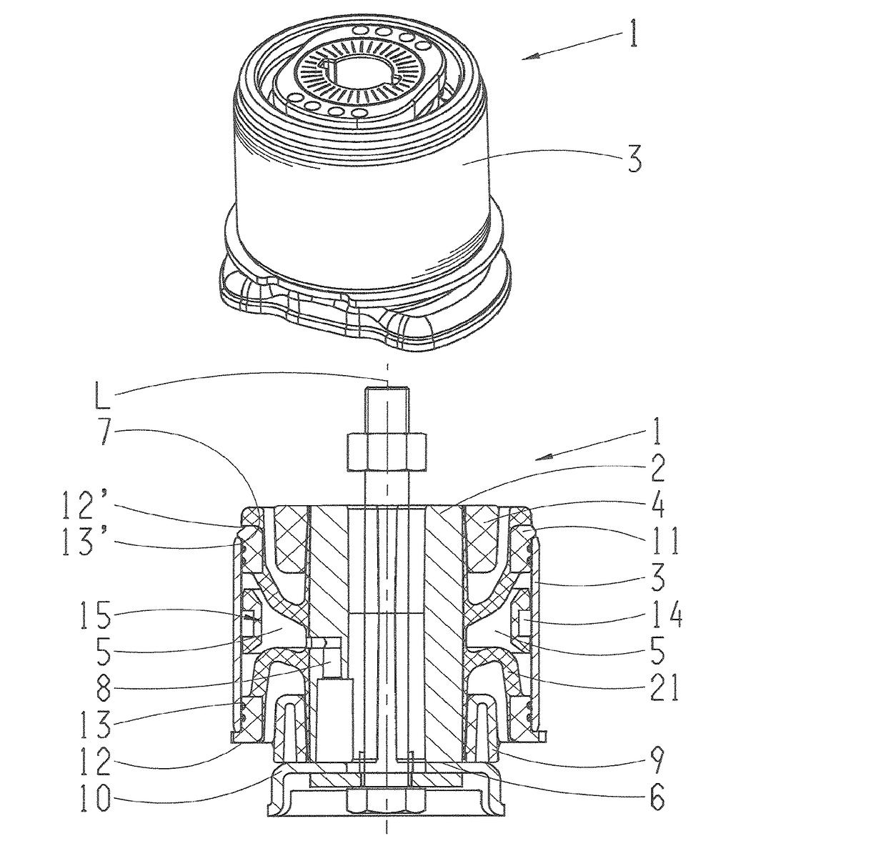
Figure 1 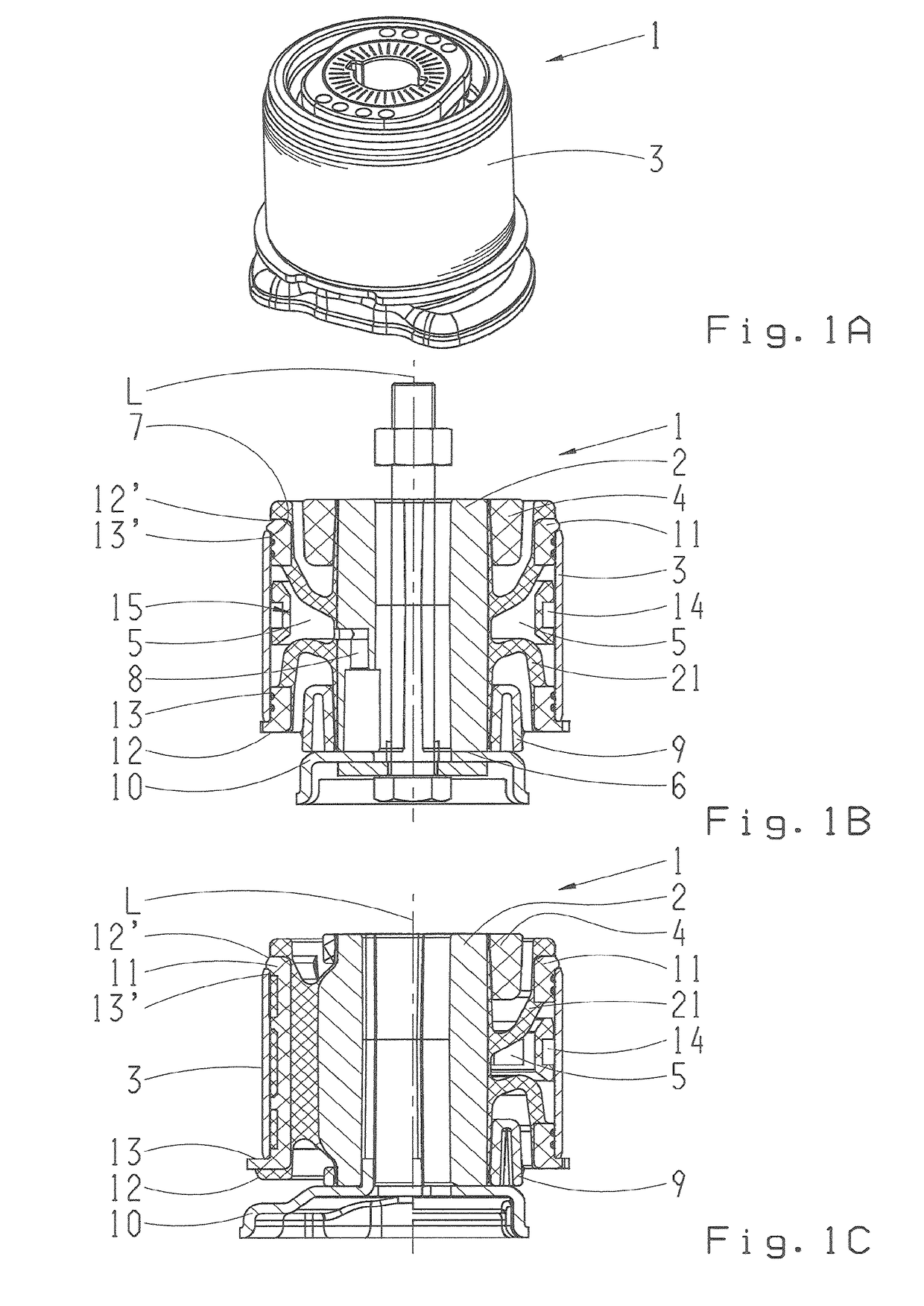
Figure 2 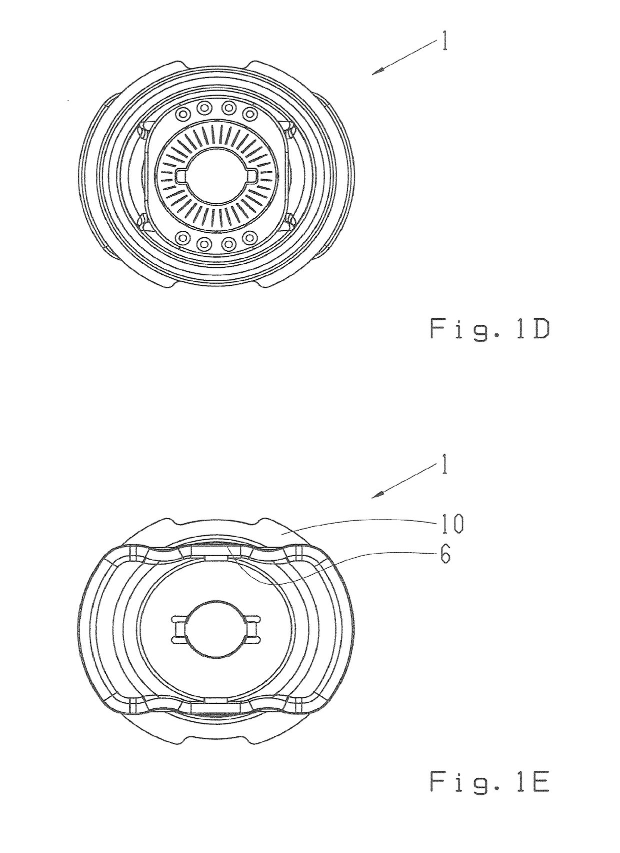
Figure 3
Abstract
Description
CROSS-REFERENCE TO RELATED APPLICATIONS
[0001] This application is a continuation application of U.S. patent application Ser. No. 14 / 778,895, filed on Sep. 21, 2015 which is a U.S. national phase of application No. PCT / EP2014 / 053208, filed Feb. 19, 2014, which claims priority from German application No. DE10 2013 204 995.1, filed Mar. 21, 2013, each of which is herein incorporated by reference in its entirety.FIELD OF THE INVENTION
[0002] The invention relates to a method for producing a bearing, in particular a hydraulic axle support bearing.BACKGROUND OF THE INVENTION
[0003] The axle support bearings known in the prior art generally have an inner part made of aluminium, a radial channel, an outer part and an elastomeric region which is arranged between the inner part and the outer part. The elastomeric region is reinforced by a steel cage or a plastic cage which has the advantage of reducing the weight of the bearing substantially. A steel cage is embedded into the rubber of the elastom...