
Turn signal lamp for bicycle

Active Publication Date: 2015-10-15
YANG KUO CHI
View PDF2 Cites 3 Cited by
  • Summary
  • Abstract
  • Description
  • Claims
  • Application Information

AI Technical Summary

Benefits of technology

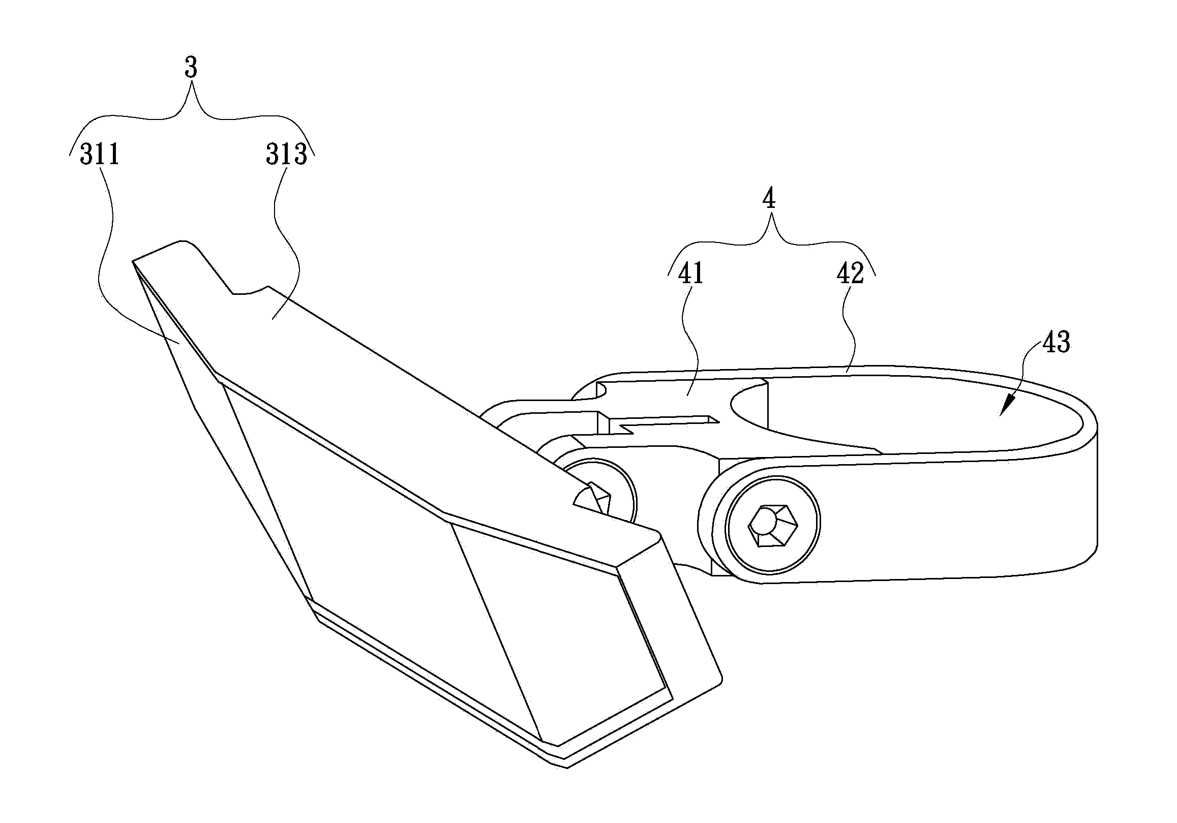
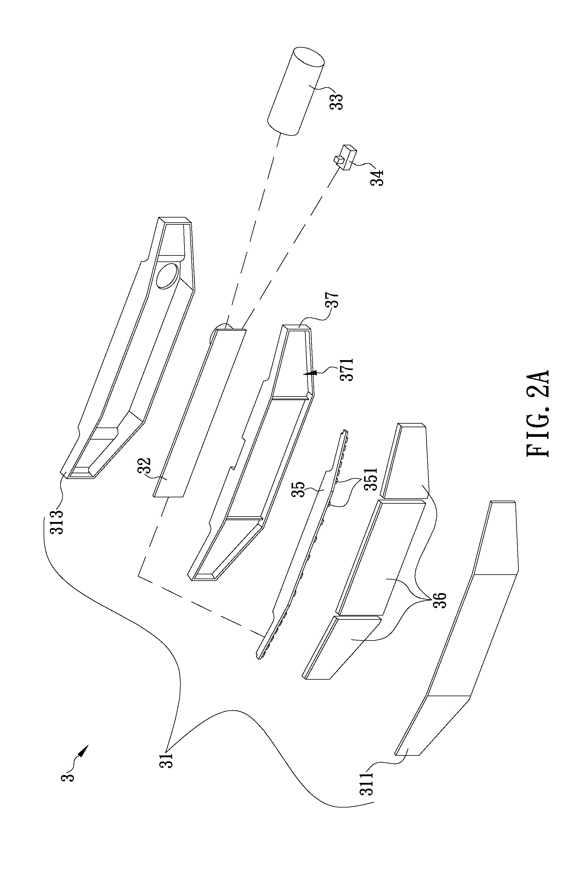
The present invention provides a turn signal lamp for bicycles that can clearly display the turning signal of the bicycle. The turn signal lamp is easy to install in various types of bicycles and is designed to improve safety during riding. The lamp includes a casing, circuit board, battery, light indication switch, light source plate, and light guide plates. The light guide plates are placed inside the casing to create a surface light that can be easily observed by drivers or riders behind the bicycle. The turn signal lamp can be mounted in either the front or back of the bicycle and is convenient to use.

Problems solved by technology

However, such turn signal lamp cannot meet the modern people's demand for simple and convenient use.
The turn signal warning effect of the existing turn signal lamp may not be presented due to the factors described above, so the existing turn signal lamp is in lack of usefulness.
Therefore, it is a primary issue to develop a product to solve the defects of the existing turn signal lamp.

Method used


Image

  • Turn signal lamp for bicycle
  • Turn signal lamp for bicycle
  • Turn signal lamp for bicycle

Examples


Embodiment Construction

[0014]Reference will now be made in detail to the exemplary embodiments of the present invention, examples of which are illustrated in the accompanying drawings. However, it should be understood that all the exemplary embodiments illustrated below are not to be construed as limited to the specific embodiments disclosed, and that modifications to the disclosed exemplary embodiments, as well as other exemplary embodiments, are intended to be included within the scope of the appended claims. These embodiments are provided so that this invention will be thorough and complete, and will fully convey the inventive concept to those skilled in the art. The relative proportions and ratios of elements in the drawings may be exaggerated or diminished in size for the sake of clarity and convenience in the drawings, and such arbitrary proportions are only illustrative and not limiting in any way. The same reference numbers are used in the drawings and the description to refer to the same or like ...


PUM


Abstract

The present invention is to provide a turn signal lamp for bicycle, which includes a casing having a front side made of transparent material, a circuit board disposed inside the casing, a battery electrically connected to the circuit board, a light indication switch disposed close to a handle of the bicycle and configured to generate an operation signal to the circuit board according to a user's operation, a light source plate disposed inside the casing and each having light units disposed thereon for receiving power and control signal from the circuit board and enabling the light units to emit light constantly or blinkingly, and at least one light guide plate disposed inside the casing and configured to form at least two surface lights from point lights emitted by the light units, so as to produce a light indication of turning right or left through the front side of the casing.

Description

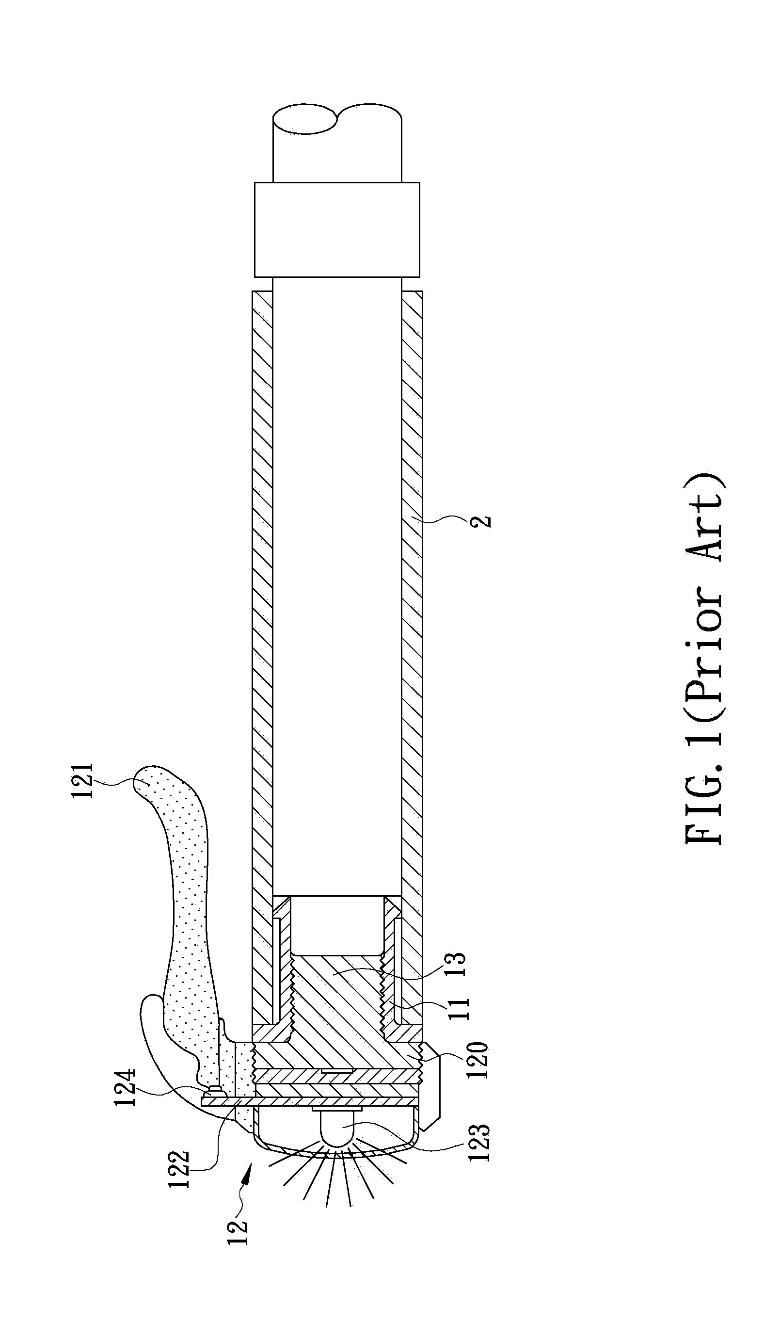
FIELD OF THE INVENTION[0001]The present invention generally relates to a turn signal lamp, more particularly to a turn signal lamp for a bicycle.BACKGROUND OF THE INVENTION[0002]In order to improve the safety for bicycle rider and reduce occurrence of the traffic accident, most bicycle manufacturers and designers make effort in equipping different types of safety devices on the bicycle. An existing turn signal lamp for bicycle in prior art is described as follows. Please refer to FIG. 1. The existing turn signal lamp includes a positioning member 11, a light emitting member 12 and a linking member 13. The positioning member 11 is disposed and positioned inside two open ends of the bicycle handle 2. The light emitting member 12 includes a base 120, a control member 121 (as dots regions shown in FIG. 1) linked to the base 120, a lighting driving circuit 122 filled in the base 120, a light unit 123 disposed on the lighting driving circuit 122, and a switch 124 disposed in the lighting ...

Claims


Application Information

Patent Timeline
IPC IPC(8): B62J6/00
CPCB62J6/005B62J6/056
Inventor YANG, KUO CHI
Owner YANG KUO CHI
Learn More