

Shielded connector
- Summary
- Abstract
- Description
- Claims
- Application Information
AI Technical Summary
Benefits of technology
Problems solved by technology
Method used
Image

Examples
first embodiment
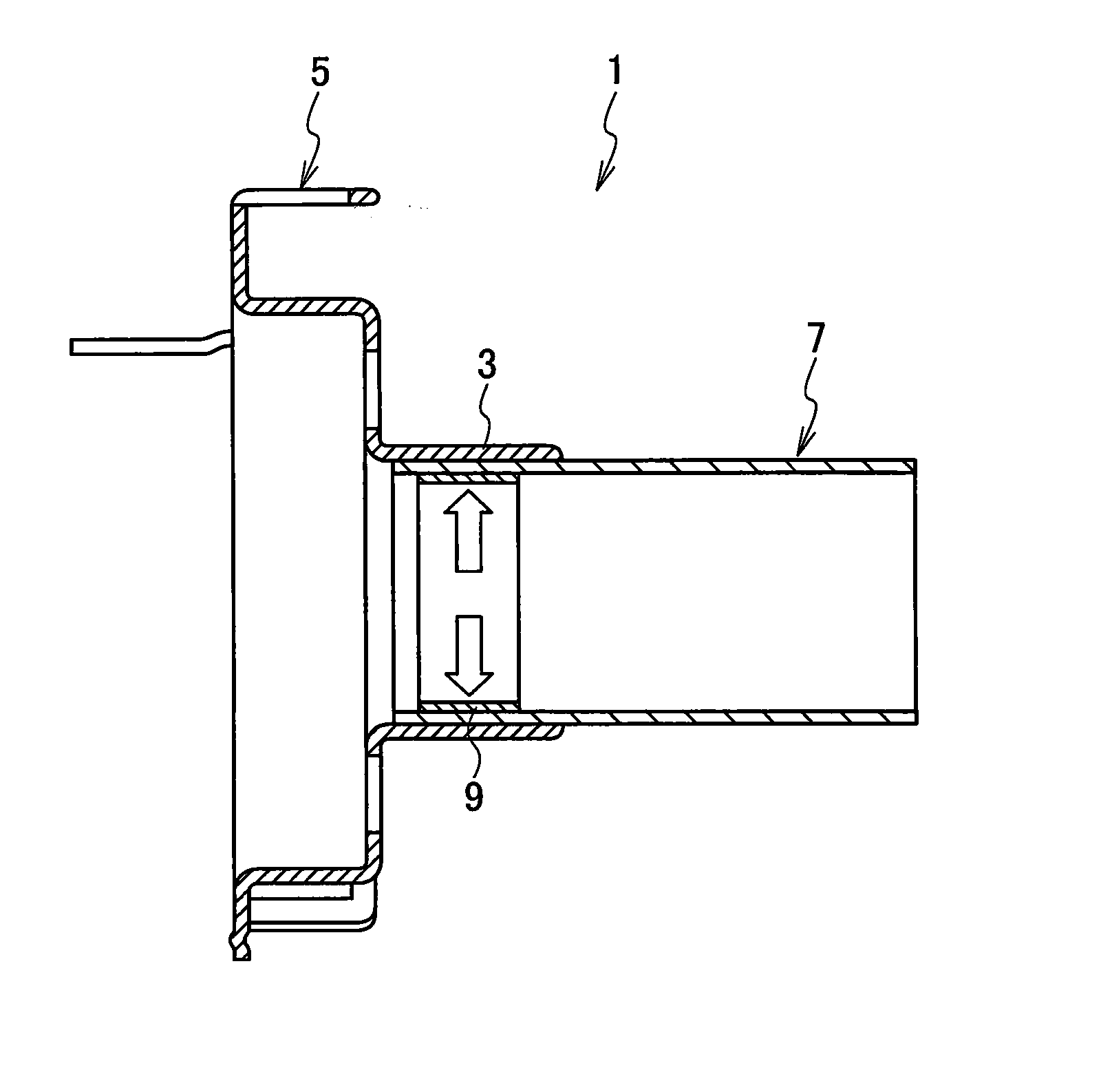
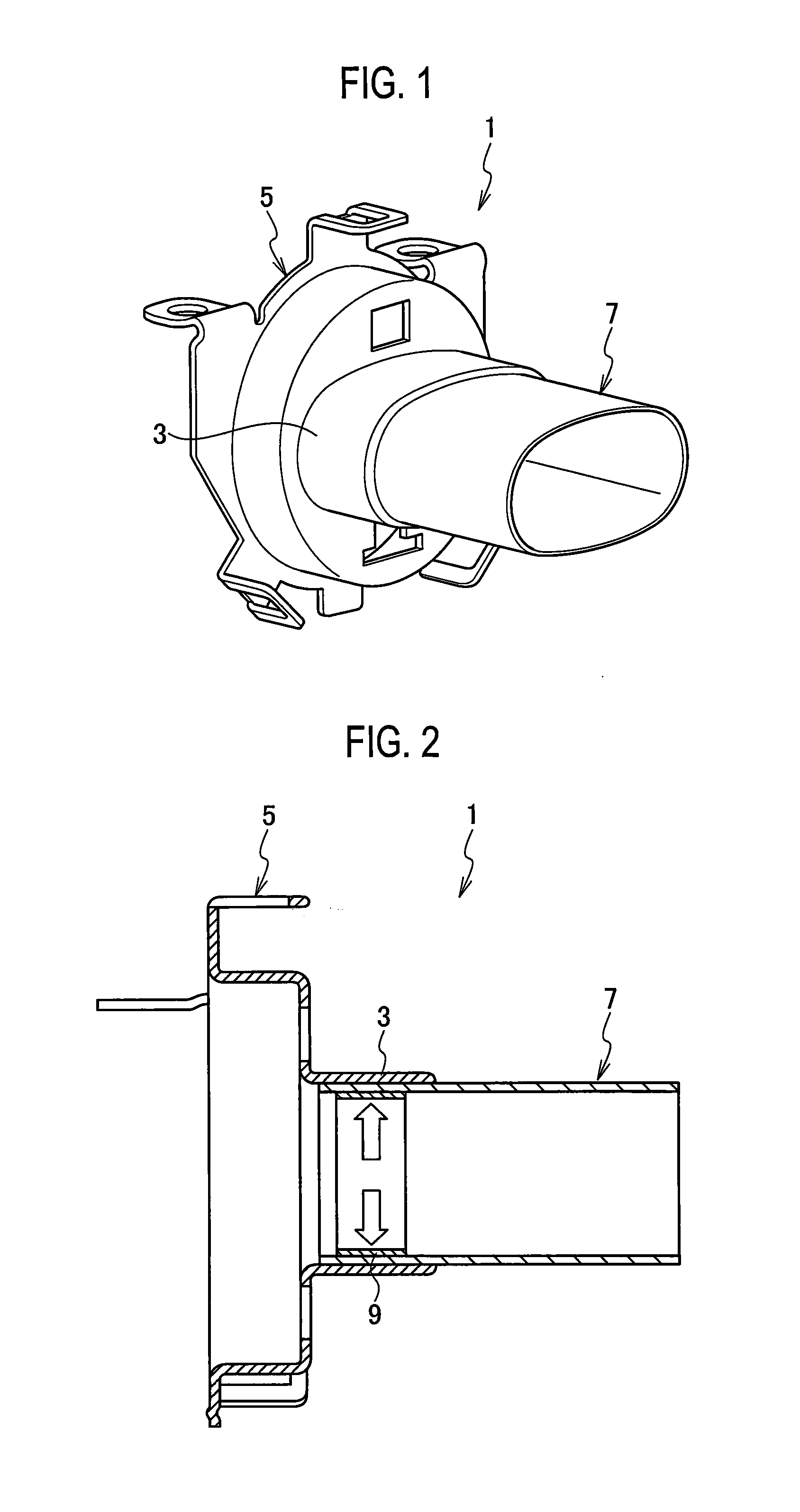
[0025]A first embodiment will be described with references to FIGS. 1 and 2.
[0026]A shielded connector 1 according to the present embodiment includes a shield shell 5 including a cylindrical portion 3, and a cylindrical shield member 7 arranged at the cylindrical portion 3.
[0027]Further, in the cylindrical portion 3, the shield member 7 is inserted in an inner circumference side, and an end portion of the shield member 7 is sandwiched and fixed between the cylindrical portion 3 and a pressing member 9 inserted in the cylindrical portion 3.
[0028]Further, the pressing member 9 presses the shield member 7 toward the cylindrical portion 3, and fixes the shield member 7 in close contact with the cylindrical portion 3. More specifically, the pressing member 9 includes a crimping ring which crimps the shield member 7 toward an inner circumference surface of the cylindrical portion 3.
[0029]In this regard, the shielded connector 1 is assembled to a wire lead-out portion side of a housing whi...
second embodiment
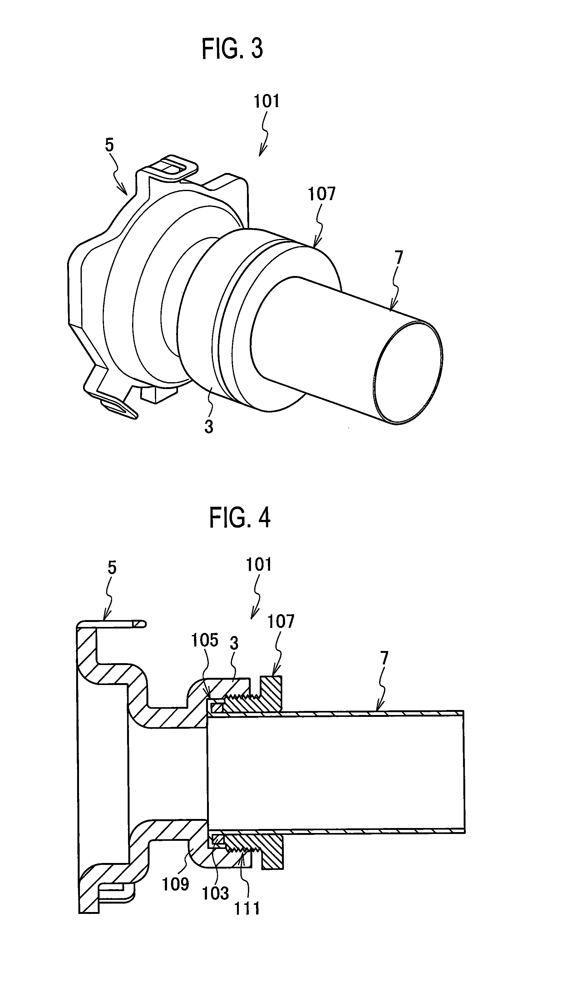
[0042]A second embodiment will be described with references to FIGS. 3 and 4.
[0043]In a shielded connector 101 according to the present embodiment, a pressing member 103 is arranged at a folded portion 105 at which an end portion of a shield member 7 is folded back toward the outer circumference.
[0044]Further, a fixing member 107 fixed to an inner circumference of a cylindrical portion 3 is arranged on an outer circumference of the shield member 7, and the pressing member 103 presses the shield member 7 toward the cylindrical portion 3 by being pressed by the fixing member 107.
[0045]Furthermore, the pressing member 103 includes a rubber seal as an elastic member which presses the shield member 7 toward an inner circumference surface of the cylindrical portion 3.
[0046]Note that the same configurations as those in the first embodiment will be assigned the same reference numerals, and a configuration and a function will not be described assuming that a reference to the first embodiment...
third embodiment
[0056]A third embodiment will be described with reference to FIGS. 5 and 6.
[0057]According to a shielded connector 201 according to the present embodiment, a pressing member 203 is arranged at a folded portion 105 at which an end portion of a shield member 7 is folded toward the outer circumference.
[0058]Further, the pressing member 203 is a wedge-shaped bush which presses the shield member 7 toward an inner circumference surface of a cylindrical portion 3 by being pressed fit to the cylindrical portion 3.
[0059]Note that the same configurations as those in the other embodiments will be assigned the same reference numerals, and a configuration and a function will not be described assuming that a reference to the other embodiments will be made. The configuration is the same as that of the other embodiments, so that a resulting effect is the same.
[0060]As illustrated in FIGS. 5 and 6, the pressing member 203 is the bush which is formed into an annular and tapered wedge. The pressing me...
PUM
 Abstract
Description
Claims
Application Information