Lens assembly and imaging apparatus
a technology of applied in the field of lens assembly and imaging apparatus, can solve the problems of difficult to ensure waterproof performance, difficult to make the o-ring sufficiently close to the outer peripheral surface, etc., and achieve the effect of improving waterproof performance and waterproof performan
- Summary
- Abstract
- Description
- Claims
- Application Information
AI Technical Summary
Benefits of technology
Problems solved by technology
Method used
Image
Examples
first embodiment
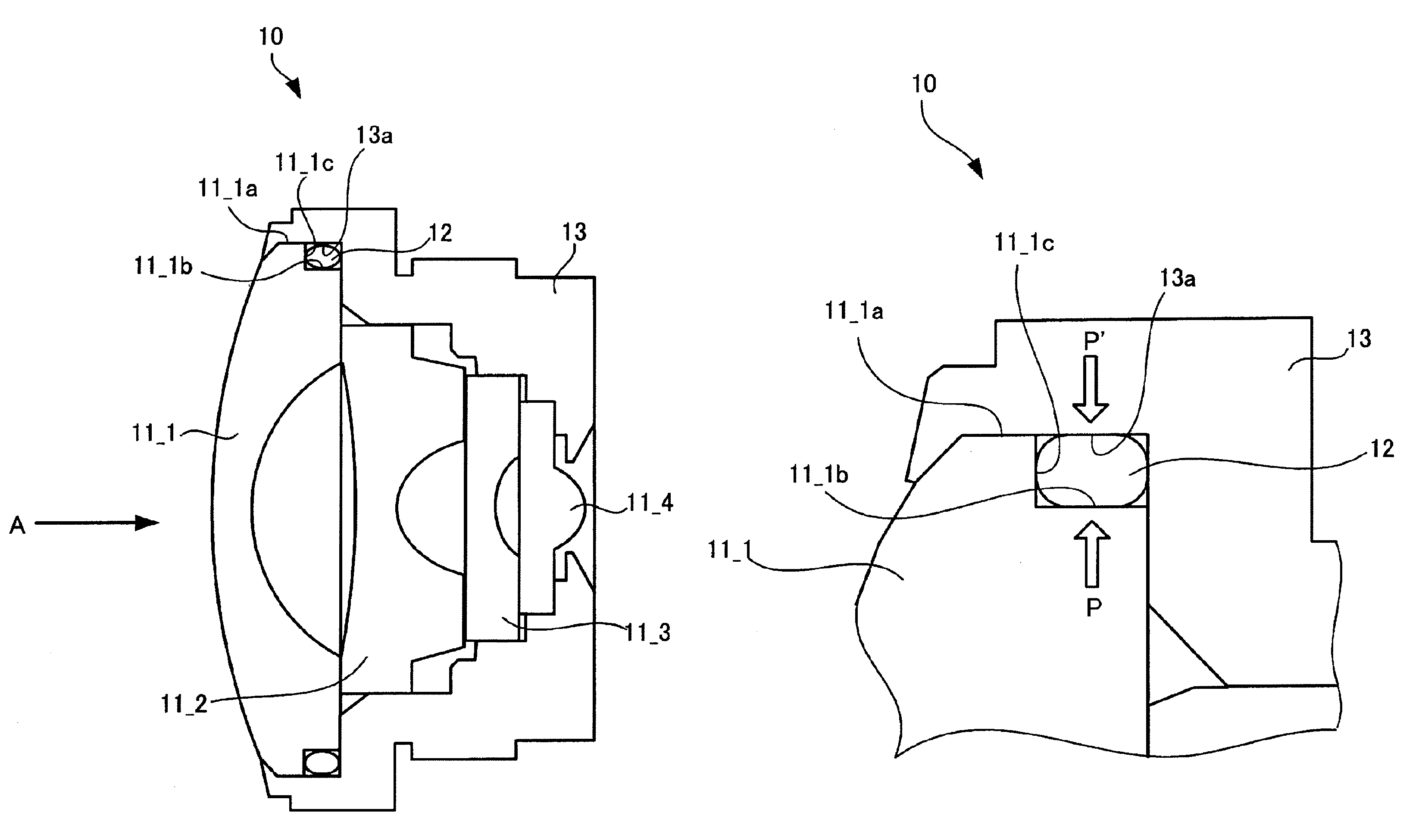
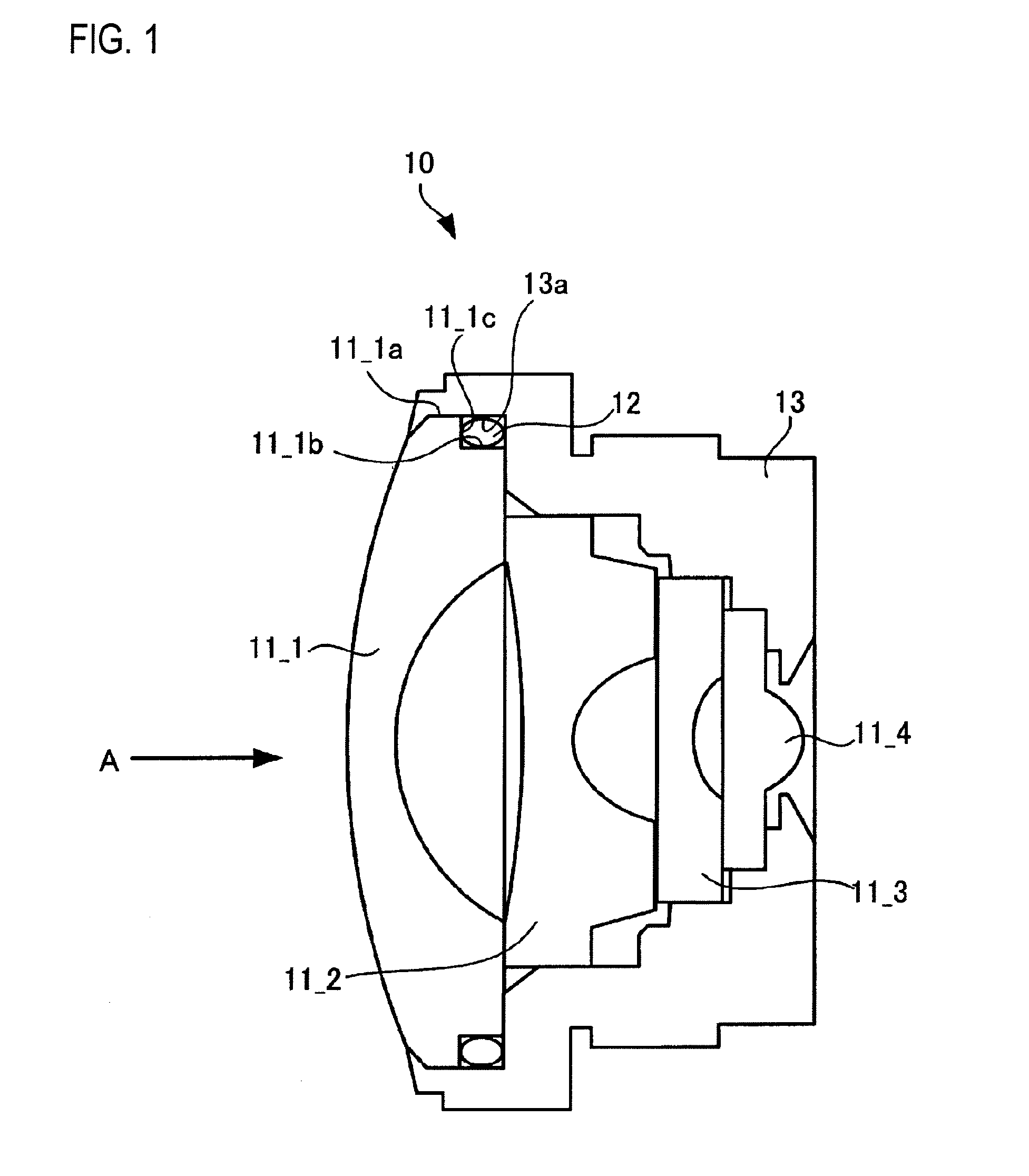
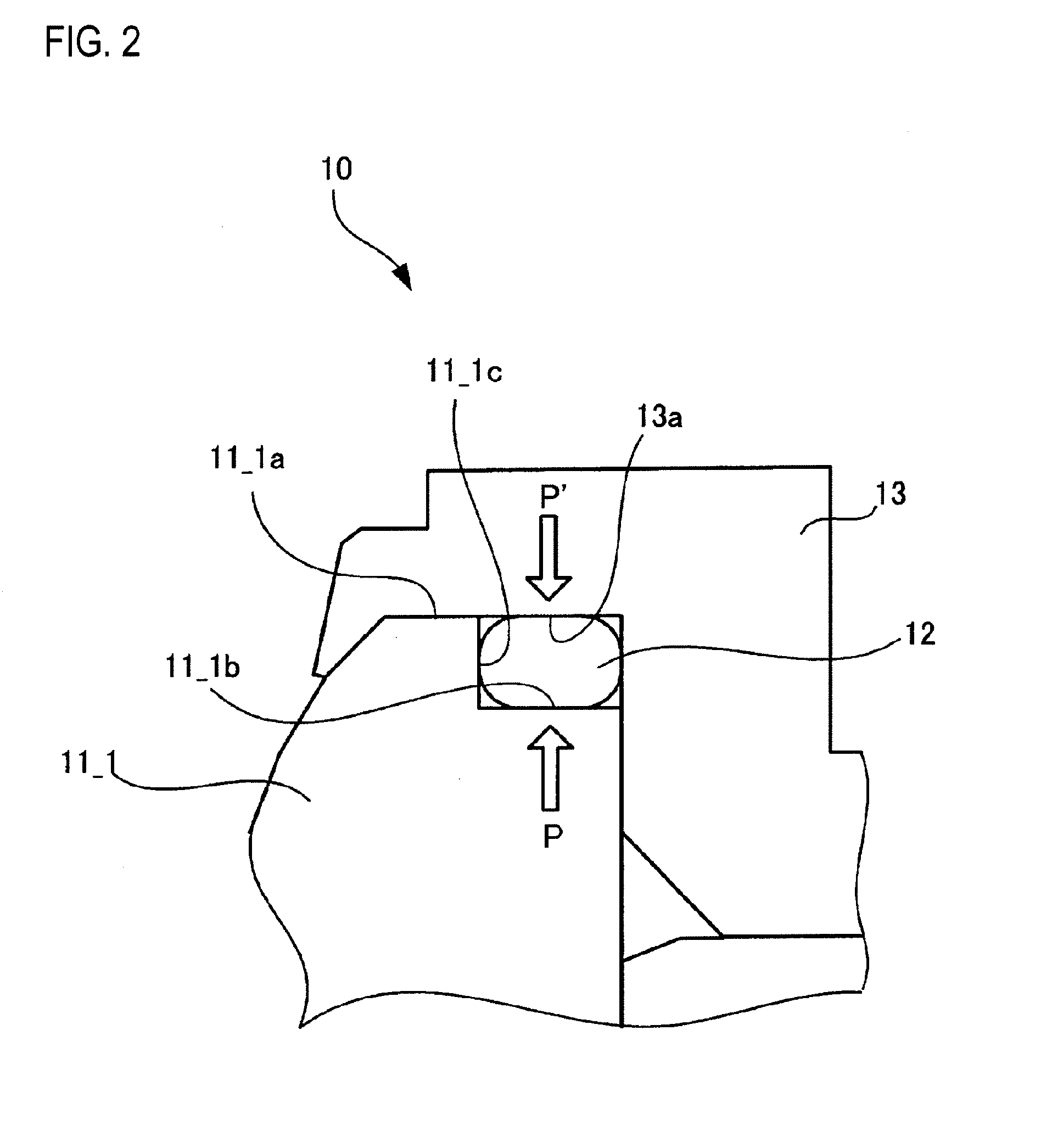
[0028]FIG. 1 is a view illustrating a section of a lens assembly according to the invention, taken along an optical axis of a taking lens. FIG. 2 is an enlarged sectional view illustrating a part, in which an O-ring is disposed, of the lens assembly shown in FIG. 1.
[0029]A lens assembly 10 according to the first embodiment shown in FIG. 1 includes a taking lens 11_1 of a first group, a taking lens 11_2 of a second group, a taking lens 11_3 of a third group, and a taking lens 11_4 in order from an incident side of subject light A. Also, as shown in FIGS. 1 and 2, the taking lens 11_1 includes a first outer peripheral surface 11_1a, a second outer peripheral surface 11_1b and an inner wall surface 13a. The second outer peripheral surface 11_1b is provided on an image side of the first outer peripheral surface 11_1a. The second outer peripheral surface 11_1b has a diameter smaller by one step than that of the first outer peripheral surface 11_1a. The wall surface 11—c is interposed bet...
second embodiment
[0033]FIG. 3 is an enlarged sectional view illustrating a part, in which an O-ring is disposed, of the lens assembly according to the invention.
[0034]Furthermore, in the following description, elements the same as those of the lens assembly 10 shown in FIGS. 1 and 2 will be referenced by the same reference numerals and signs, and differences therebetween will be described.
[0035]As compared with the lens assembly 10 shown in FIGS. 1 and 2, the lens assembly 20 shown in FIG. 3 is different in that the second outer peripheral surface 11_1b is replaced with a second outer peripheral surface 11_1d to be described below.
[0036]The second outer peripheral surface 11_1d shown in FIG. 3 is smoothed by applying paint thereto. As such paint, it is possible to appropriately use paint containing at least one selected from epoxy, urethane, silicone, acryl, melamine, vinyl, amino, alkyd, polyester, fluorine, and enamel.
[0037]In the lens assembly 20 according to the second embodiment, the second out...
third embodiment
[0038]FIG. 4 is an enlarged sectional view illustrating a part, in which an O-ring is disposed, of the lens assembly according to the invention.
[0039]Furthermore, in the following description, elements the same as those of the lens assembly 10 shown in FIGS. 1 and 2 will be referenced by the same reference numerals and signs, and differences therebetween will be described.
[0040]As compared with the lens assembly 10 shown in FIGS. 1 and 2, the lens assembly 30 shown in FIG. 4 is different in that the inner surface 13a of the lens frame 13 is replaced with an inner surface 13b to be described below.
[0041]Lubricating paint is applied onto a part, being in contact with the first outer peripheral surface 11_1a and the O-ring 12, of the inner surface 13b of the lens frame 13 shown in FIG. 4. The part, being in contact with the O-ring 12, of the inner surface 13b of the lens frame 13 is smoothed by the lubricating paint. In this manner, the O-ring 12 having the smooth surface is pressed by...
PUM
 Abstract
Description
Claims
Application Information
 - R&D Engineer
- R&D Manager
- IP Professional
- Industry Leading Data Capabilities
- Powerful AI technology
- Patent DNA Extraction
Browse by: Latest US Patents, China's latest patents, Technical Efficacy Thesaurus, Application Domain, Technology Topic, Popular Technical Reports.
© 2024 PatSnap. All rights reserved.Legal|Privacy policy|Modern Slavery Act Transparency Statement|Sitemap|About US| Contact US: help@patsnap.com


