
Photovoltaic power generation system

a photovoltaic power generation and photovoltaic technology, applied in the direction of cycle equipment, secondary cell servicing/maintenance, light to electrical conversion, etc., can solve the problems of inefficiency of vehicular photovoltaic power generation system operation, inability to check the level of remaining batteries, etc., to ensure waterproof performance of the cover, simplify the management of the assembling process, and ensure the effect of waterproof performan

Inactive Publication Date: 2011-09-29
HONDA MOTOR CO LTD
View PDF4 Cites 18 Cited by
  • Summary
  • Abstract
  • Description
  • Claims
  • Application Information

AI Technical Summary

Benefits of technology

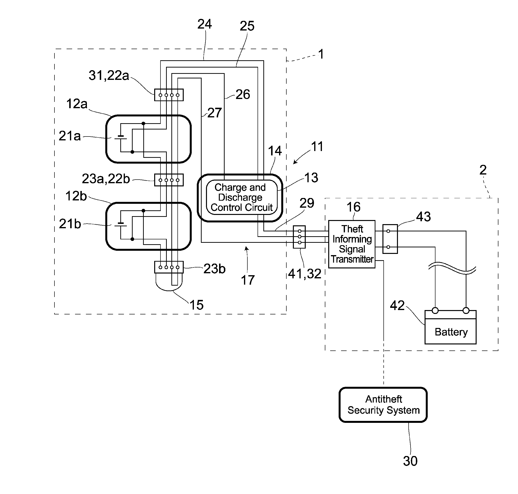
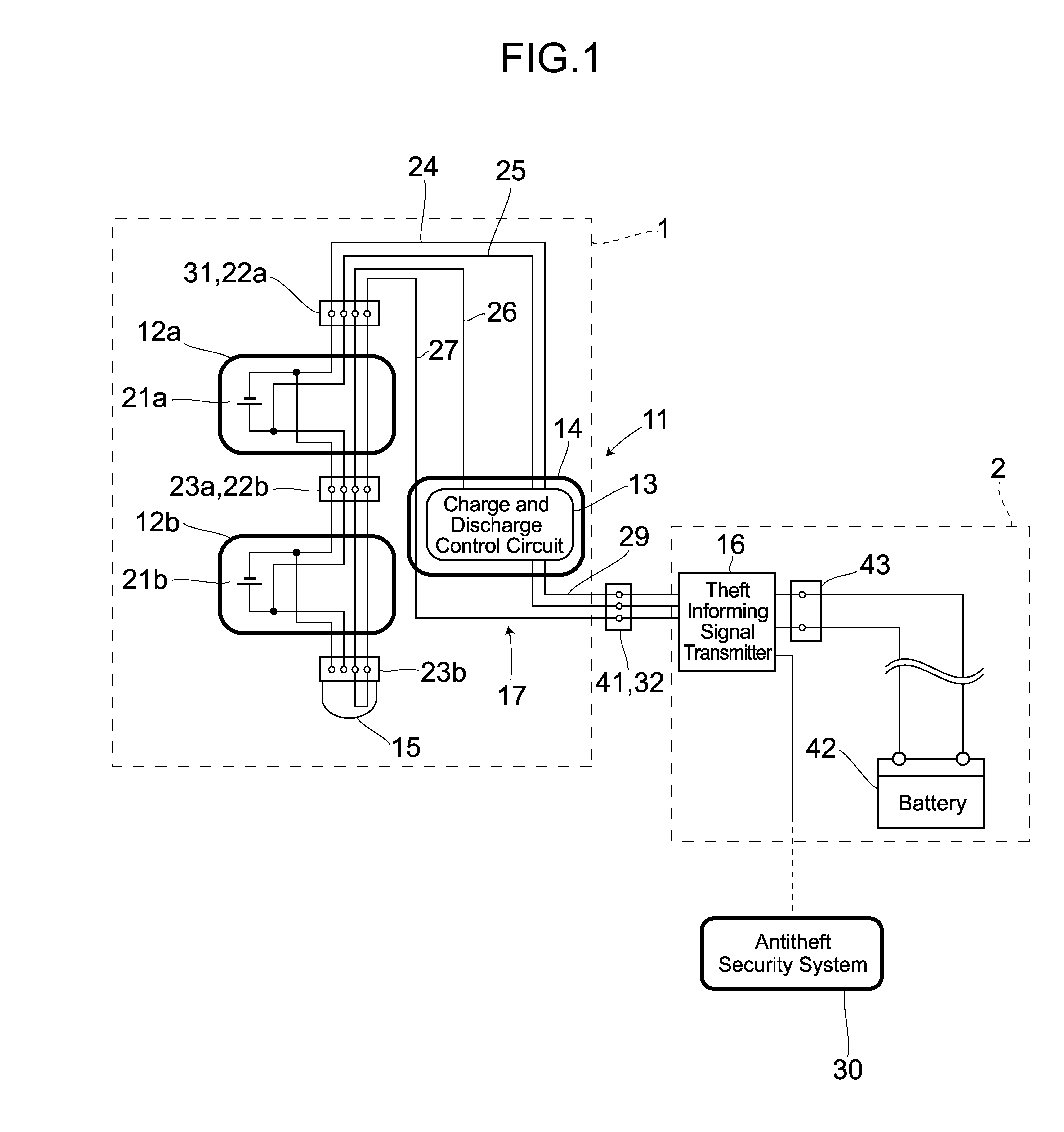
[0008]Therefore, with the view of the problem described above, it is an object of the present invention to provide a for making it possible to check at once the electricity generated by the solar cells and a remaining battery level, thereby enabling the photovoltaic power generation system to be efficiently operated.
[0009]Besides, it is also an object of the present invention to provide a photovoltaic power generation system which can realize more reliable waterproof performance.
[0010]In order to attain the object described above, as a first aspect of the present invention, there is provided a photovoltaic power generation system provided to charge a battery of a vehicle and is equipped with solar cells for feeding electromotive force to the battery. The photovoltaic power generation system is equipped with a display unit for making it possible to view the remaining battery level and the electricity generated by the solar cells.

Problems solved by technology

However, the vehicular photovoltaic power generation system according to the conventional art described above has the following problem.
If a user does not operate the button at all, however, the remaining battery level cannot be checked.
Therefore, if the electricity of the solar cells and the remaining battery level cannot be checked at once, the vehicular photovoltaic power generation system cannot be efficiently operated.

Method used


Image

  • Photovoltaic power generation system
  • Photovoltaic power generation system
  • Photovoltaic power generation system

Examples


embodiment 2

[0102]Next is a description of a preferred second embodiment on the cover for a solar cell panel proposed by the present invention. FIG. 10 to FIG. 16 all show a solar panel module 101 corresponding to the forgoing solar cell modules 12a, 12b. In each of these figures, numeral symbol 102 a bendable, flexible, platy and sheet-like solar cell panel and a pair of conductive lead wires 103 extend from one side of the solar cell panel 102. The solar cell module 101 in the present embodiment has a structure in which the solar cell panel 102 is sandwiched to be protected by a transparent cover 105 produced by molding a resin material such as polycarbonate (PC) or the like and a flexible elastic cover 106.

[0103]A cover 107 acting as a an outer chassis of the solar cell module 101 (corresponding to the foregoing module main body 71) has a approximately hexahedral, flat and boxy shape and is formed with the transmssive cover 105 on its top face and with the elastic cover 106 on its bottom and...


PUM

PropertyMeasurementUnit
thicknessaaaaaaaaaa
electromotive forceaaaaaaaaaa
sunlight transmission propertyaaaaaaaaaa

Abstract

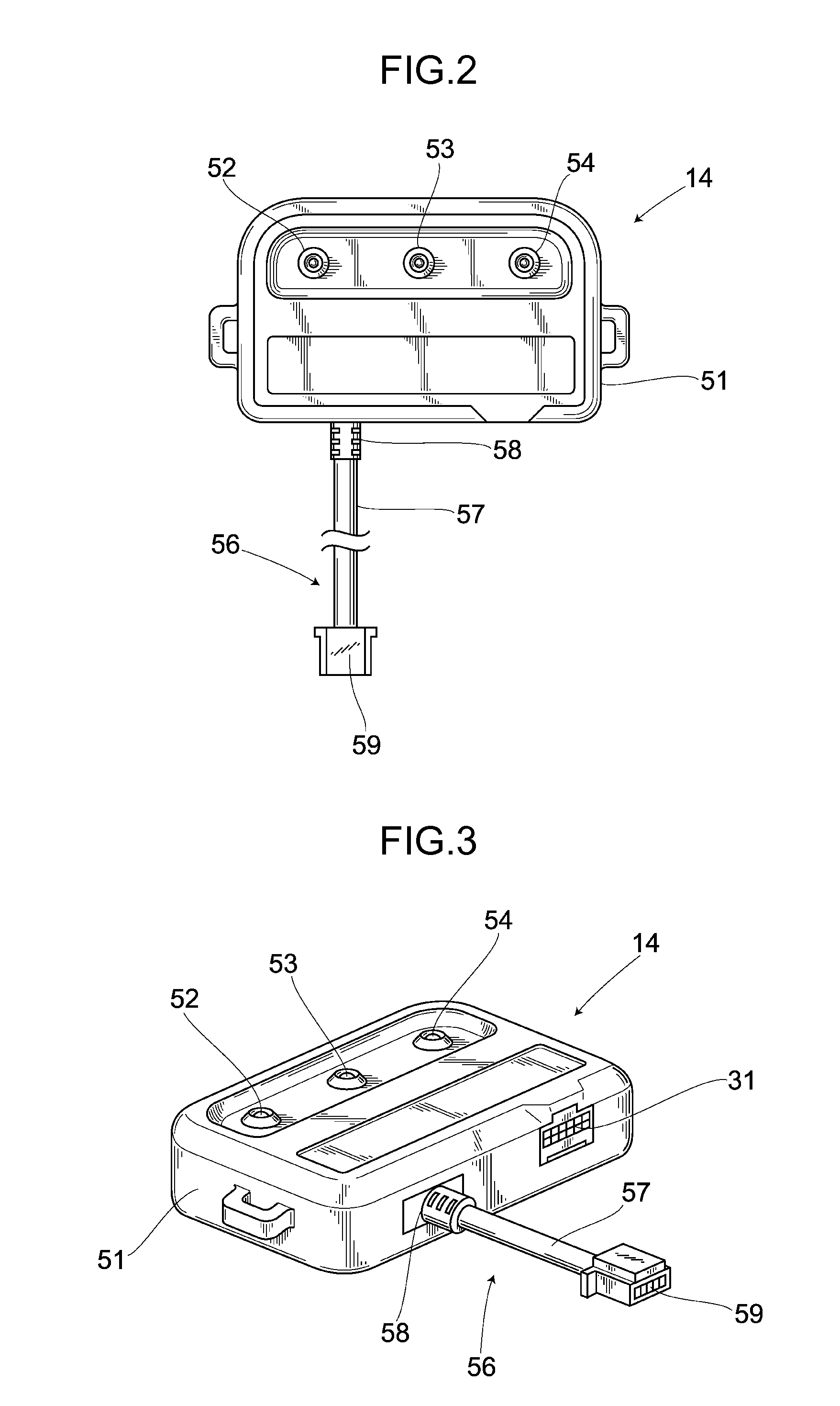
A photovoltaic power generation system in which an electricity generated by solar cells and a remaining battery level can be checked at once, thus enabling the photovoltaic power generation system to be efficiently operated. The photovoltaic power generation system is provided to charge a battery of a vehicle and is equipped with solar cells for feeding an electromotive force to the battery. The photovoltaic power generation system includes LEDs to make the remaining battery level and the electricity generated by the solar cells visible. Without taking the trouble to prepare a measuring instrument or to push a button of an indicator, a user of the vehicle can immediately check the remaining battery level and the electricity generated by the solar cells by visually checking the display of the LEDs, thus enabling the photovoltaic power generation system to be efficiently operated.

Description

BACKGROUND OF THE INVENTION[0001]1. Field of the Invention[0002]The present invention relates to a photovoltaic power generation system incorporated in a vehicle body cover for protecting a vehicle and is provided to charge a battery of the vehicle.[0003]2. Description of the Related Art[0004]As this kind of vehicular photovoltaic power generation system, it has been proposed, e.g., in Japanese examined utility model application publication No. H1-15531, that light receiving surfaces of solar cells are exposed on an outer surface of a vehicle body cover for covering a vehicle to be protected and thereby the electromotive force of the solar cells is supplied to a ventilating device especially when the sun is shining. Such a photovoltaic power generation system is used also to apply auxiliary charge to a battery mounted on, e.g., a two-wheeled vehicle (a saddle-straddling type vehicle) and also is used to feed electric power to parts of the two-wheeled vehicle carrying a secondary bat...

Claims


Application Information

Patent Timeline
Patent Type & Authority Applications(United States)
IPC IPC(8): H01M10/46
CPCB60L8/003B60L11/1824B60L11/1838B60L2230/16B60L2250/10B60L2270/36Y02T90/121Y02T10/7005Y02T10/7083Y02T10/7094Y02T90/128Y02T90/14Y02T90/163B62J19/00B60L53/30B60L53/305B60L53/62Y02T10/70Y02T10/7072Y02T90/12Y02T90/16
Inventor HOSHI, TOMOHIROOSHITA, AKIRAISHIDA, NORIYUKI
Owner HONDA MOTOR CO LTD
Learn More