
Pressing jig comprising magnet and battery module comprising the same

Pending Publication Date: 2021-07-22
LG ENERGY SOLUTION LTD
View PDF0 Cites 2 Cited by
  • Summary
  • Abstract
  • Description
  • Claims
  • Application Information

AI Technical Summary

Benefits of technology

The present invention aims to improve the pressing force provided to battery cells by using a magnet in a pressing jig for mechanically pressing battery cells. This will lead to better battery performance by providing a uniform pressing force. Additionally, the invention includes a battery module with the pressing jig that shields the magnetism to prevent it from interfering with other device configurations and ensuring safety.

Problems solved by technology

However, it is limited in the pressing according to a mechanical pressure, so there are limits in improving the capacity and lifespan performance.

Method used


Image

  • Pressing jig comprising magnet and battery module comprising the same
  • Pressing jig comprising magnet and battery module comprising the same
  • Pressing jig comprising magnet and battery module comprising the same

Examples


preparation example

[0106]82 wt % of LiNi0.6Co0.2Mn0.2O2 as a positive active material, 9 wt % of carbon black as a conductive material, and 9 wt % of PVdF as a binder are input to NMP that is a solvent, and they are mixed to manufacture a positive electrode slurry, which is then applied at a thickness of 50 μm to an aluminum current collector with a thickness of 20 μm, and is then dried at a temperature of 130° C. to thus manufacture a positive electrode.

[0107]A Li metal with a thickness of 50 μm is used as a negative electrode.

[0108]A stack cell of a positive electrode / negative electrode / positive electrode is manufactured in a form of providing respective sides of a porous polyethylene base, and an SRS separation film in which an organic / inorganic mixed layer in which a binder (PVdF) and an inorganic material particle (Al2O3) are mixed at a weight ratio of 2:8 between the positive electrode and the negative electrode, and an electrolyte solution in which 1 M of LiPF6 is melted in a carbonate solvent ...

example 1

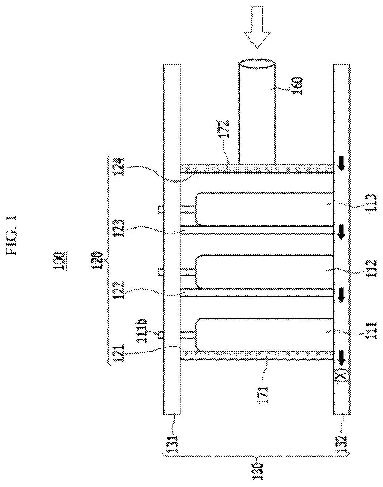
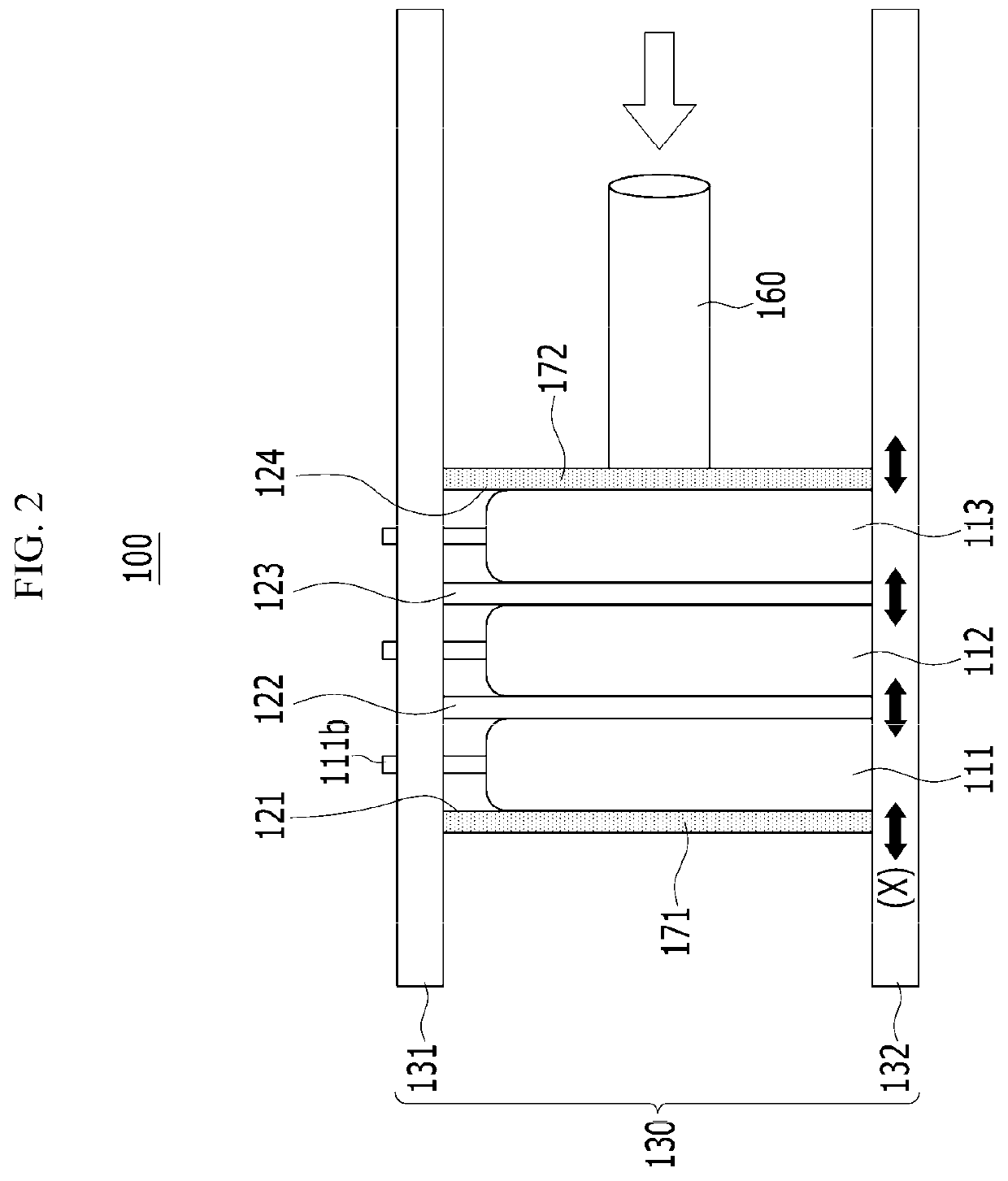
[0109]A pressing jig as shown in FIG. 1 including three battery cells manufactured according to the preparation example is prepared, and it is installed in the battery module case of FIG. 4.

[0110]Neodymium magnets with magnetic force of 2000 gauss are attached to the pressing plates provided on the outermost side of the pressing jig so that opposite polarities may face each other.

[0111]Further, mechanical pressing (pressing force: 0.80 MPa) is performed by the pressing jig.

example 2

[0112]Pressing of the battery cell is performed in a like manner of Example 1, except that neodymium magnets with a magnetic force of 3500 gauss are attached to pressing plates provided on the outermost sides of the pressing jig so that the opposite polarities may face each other as in Example 1.


PUM


Abstract

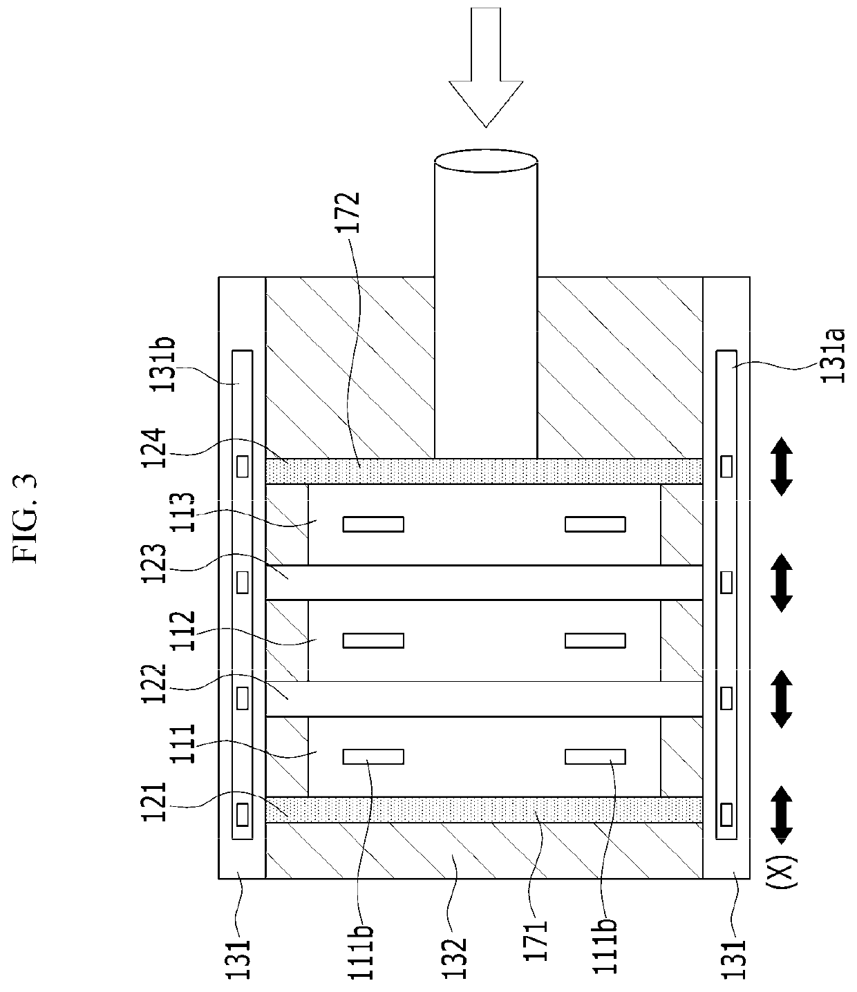
The present invention discloses a pressing jig for pressing a battery cell, and a battery module including a module case in which a plurality of battery cells are included while installed in the pressing jig, wherein the pressing jig includes a presser including a plurality of pressing plates provided on outermost portions of a plurality of battery cells and among them and separating a space for receiving a plurality of battery cells, and performing pressing on a plurality of battery cells, and pressing frames connecting the pressing plates on upper portions and lower portions of the pressing plates, wherein all the pressing plates or the pressing plates excluding one pressing plate provided on an outermost portion on one side may move in a horizontal direction as the pressing direction, while connected to the pressing frames.

Description

TECHNICAL FIELD[0001]The present invention relates to a pressing jig including a magnet, and a battery module including the same.BACKGROUND ART[0002]In general, a battery signifies a device including an electrochemical cell for supplying a potential between at least one set of terminals and a set of cells.[0003]The terminals of the battery may be electrically connected to, for example, a DC load, and may supply energy that is a voltage to the load. The battery includes a dry cell, a wet cell (e.g., a lead-acid cell), and a device for converting a chemically-usable electromotive force into a current.[0004]From among the batteries, a secondary battery is made of an electrode assembly of a three-layered structure of a positive electrode plate / separator / negative electrode plate or a multi-layered structure of at least five layers of a positive electrode plate / separator / negative electrode plate / separator / positive electrode plate, and putting the electrode assembly into a pouch, and the s...

Claims


Application Information

Patent Timeline
IPC IPC(8): H01M10/058H01M50/24H01M50/547H01M10/0525H01M50/211H01M50/204H01M50/227H01M50/271
CPCH01M10/058H01M50/24H01M50/211H01M10/0525H01M50/547Y02E60/10H01M10/0481Y02P70/50H01M50/204H01M50/227H01M50/271H01M50/121H01M50/124
Inventor YUN, HYUNWOONGHAH, HOEJINYOON, JONG KEON
Owner LG ENERGY SOLUTION LTD
Learn More