Sheet discharging device and sheet postprocess apparatus using the same

Active Publication Date: 2006-09-21
NISCA KK
View PDF7 Cites 28 Cited by
  • Summary
  • Abstract
  • Description
  • Claims
  • Application Information

AI Technical Summary

Benefits of technology

[0012] The present invention comprises switchback transferring means comprising a conveying belt provided between a sheet discharging port and a tray, and a plate-like guide member located opposite a belt surface to convey a sheet from the sheet discharging port of the conveying belt to the tray. The conveying belt and the plate-like guide member are arranged so that a tray-side end of each of the conveying belt and plate-like guide member can pivot around its sheet discharging port-side end in a vertical direction. The plate-like guide member has pressing force applying means for depressing the conveying belt. This reduces the pressing force of the pressing force applying means to convey the sheet onto the belt, while increasing the pressing force to convey the sheet off the belt. The sheet is thus reliably conveyed onto the tray. When the sheet is conveyed into the tray, the belt contacts sheets stacked on the tray under a weak pressing force to avoid damage to the sheets, f

Problems solved by technology

However, with increases in the speed of the image forming apparatus and in the number of colors used in the apparatus, sheets are more likely to be curled at high temperature.
Further, sheets the surfaces of which are coated exert only a small frictional force and are thus difficult to convey.
When the caterpillar belt is pivotably hung between the sheet discharging port and the tray and moved in the vertical direction depending on the number of sheets loaded on the tray, the following problems may occur.
For design conditions for the conveyance guide and belt, it is difficult to set stable conveyance conditions for a wide variety of sheets such as thin paper, which is likely to be curled, and glossy paper, the surface of which is coated.
With thin sheets, whic

Method used


Image

  • Sheet discharging device and sheet postprocess apparatus using the same
  • Sheet discharging device and sheet postprocess apparatus using the same
  • Sheet discharging device and sheet postprocess apparatus using the same

Examples


Embodiment Construction

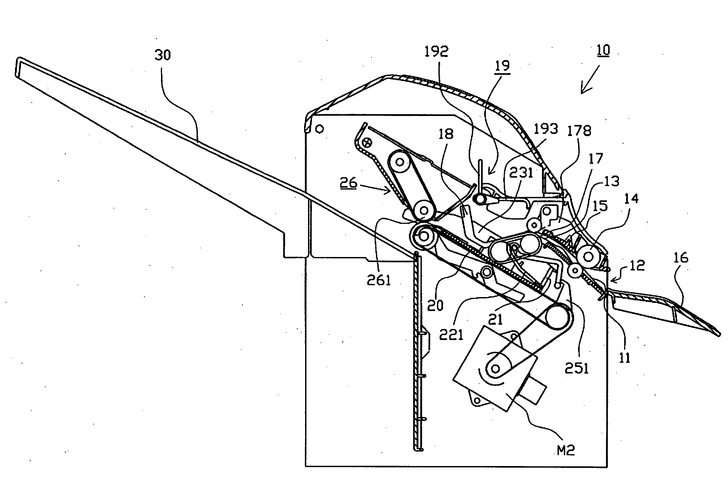
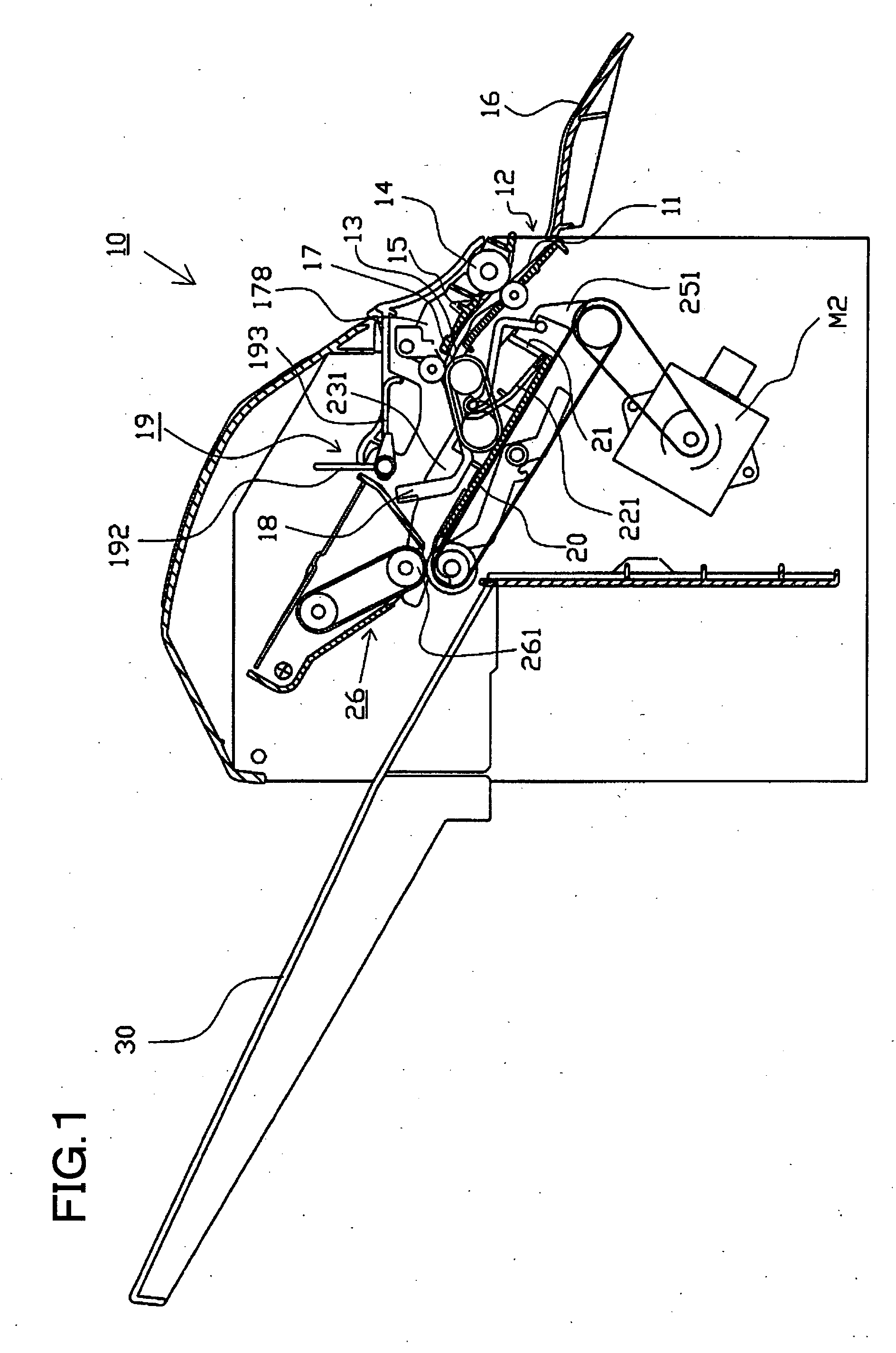
[0030] The present invention will be described below on the basis of an illustrated embodiment. FIG. 1 shows a postprocess apparatus in accordance with the present invention which executes a postprocess such as sheet binding on printed sheets (hereinafter referred to as sheets) formed using an image forming apparatus. Description will be given below of the postprocess apparatus to which the present invention is applied.

Image Forming System

[0031] The postprocess apparatus in accordance with the present invention is connected to a sheet discharging port in the image forming apparatus (not shown in the drawings) to sequentially receive sheets on which images have been formed. The postprocess apparatus then executes a “sheet binding process,” a “jog process,” and a “sheet conveying process” on the received sheets. The image forming system is composed of an image forming apparatus main body comprising a copier, a print function, and a facsimile function, and the postprocess apparatus,...


PUM


Abstract

A sheet discharging device has a conveying weight for pressing a conveyed sheet to a caterpillar belt. The pressing force of the weight is increased both when the sheet is discharged from the caterpillar belt to a placement tray, and when the sheet is switched back and conveyed to the bottom of the caterpillar belt. The pressing force of the weight is increased concurrently with the driving of a paddle provided at an outlet of the placement tray. The pressing force is increased by a rubber piece provided on a paddle driving shaft that rotates out of phase with the paddle, so as to engage and press the conveying weight at a predetermined time. The device is capable of reliably conveying a wide variety of sheets onto a tray and transferring the conveyed sheets to a predetermined tray position.

Description

BACKGROUND OF THE INVENTION AND RELATED ART STATEMENT [0001] The present invention relates to a sheet discharging device that sequentially places sheets on which images are formed using an image forming apparatus such as a printer, copier, or a printing machine, at a predetermined position on a tray, and a sheet postprocess apparatus that executes a postprocess such as stapling, punching, or stamping on the sheets placed on the tray. [0002] To automate a series of processes including copying and printing, postprocess apparatuses are commonly used which temporarily place sheets on which images are formed using an image forming apparatus, on a tray and which then execute a postprocess such as stapling, punching, or stamping on the sheets. The sheets (or a bundle of sheets) postprocessed on the temporary tray are then accommodated in a downstream accumulating tray. When the sheets are thus conveyed to the tray, the correct postprocess can be achieved only if the sheets are orderly tran...

Claims


Application Information

Patent Timeline
IPC IPC(8): B65H33/04
CPCB42C1/12B65H29/14B65H31/36B65H2404/268B65H2404/6942B65H2801/27
Inventor SAITO, TAKASHISHIMURA, MAKOTOTAKAHASHI, MASAYAHANAWA, YUJI
Owner NISCA KK
Why Eureka
Try Eureka