
Process of fabricating prepreg sheet for printed-wiring board and device of fabricating prepreg sheet for printed-wiring board

Inactive Publication Date: 2012-03-15
PANASONIC INTELLECTUAL PROPERTY MANAGEMENT CO LTD
View PDF4 Cites 3 Cited by
  • Summary
  • Abstract
  • Description
  • Claims
  • Application Information

AI Technical Summary

Benefits of technology

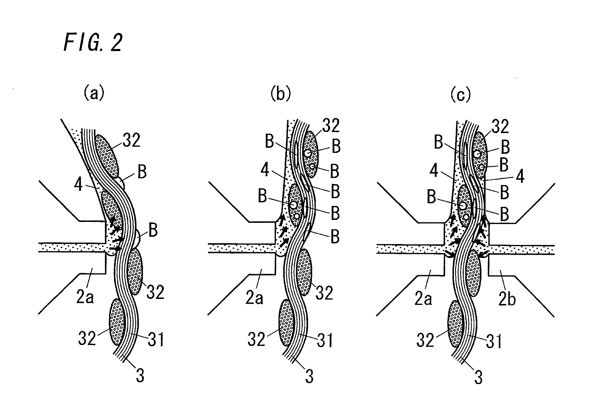
[0010]In view of the above insufficiency, the present invention has been aimed to propose a process and a device of fabricating a prepreg for a printed circuit board which are capable of controlling respective thicknesses of resin layers on the opposite surfaces of a resultant prepreg, and of improving productivity, yet sufficiently removing air bubbles from the resultant prepreg.
[0022]According to the device of fabricating a prepreg for a printed circuit board recited in claim 6, each of the first dispenser and the second dispenser is a roll coater. Therefore, the coating head defined by the periphery of the roller is pressed onto the substrate sheet in a surface contact manner. Therefore, a region receiving the pressing force can be expanded and thus air bubbles in the resin fluid can be successfully removed. Consequently, it can be successfully prevented that air bubbles are entrapped in the resultant prepreg.

Problems solved by technology

Therefore, it is difficult to independently control thicknesses of respective resin layers on the opposite surfaces of the substrate sheet.
However, in contrast to the process of impregnating the substrate sheet with the resin fluid, coating the surfaces one by one is likely to cause insufficient impregnation of the resin fluid and remaining of air bubbles inside of the resin fluid.
Consequently, implementation of this process requires a complicated device.

Method used


Image

  • Process of fabricating prepreg sheet for printed-wiring board and device of fabricating prepreg sheet for printed-wiring board
  • Process of fabricating prepreg sheet for printed-wiring board and device of fabricating prepreg sheet for printed-wiring board
  • Process of fabricating prepreg sheet for printed-wiring board and device of fabricating prepreg sheet for printed-wiring board

Examples


first embodiment

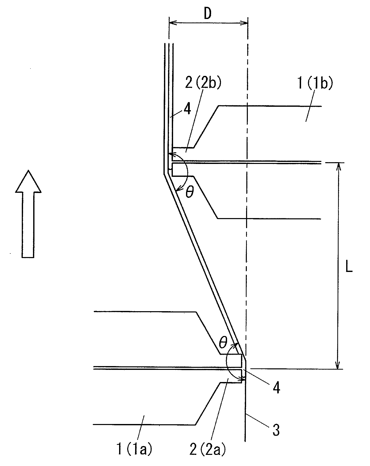
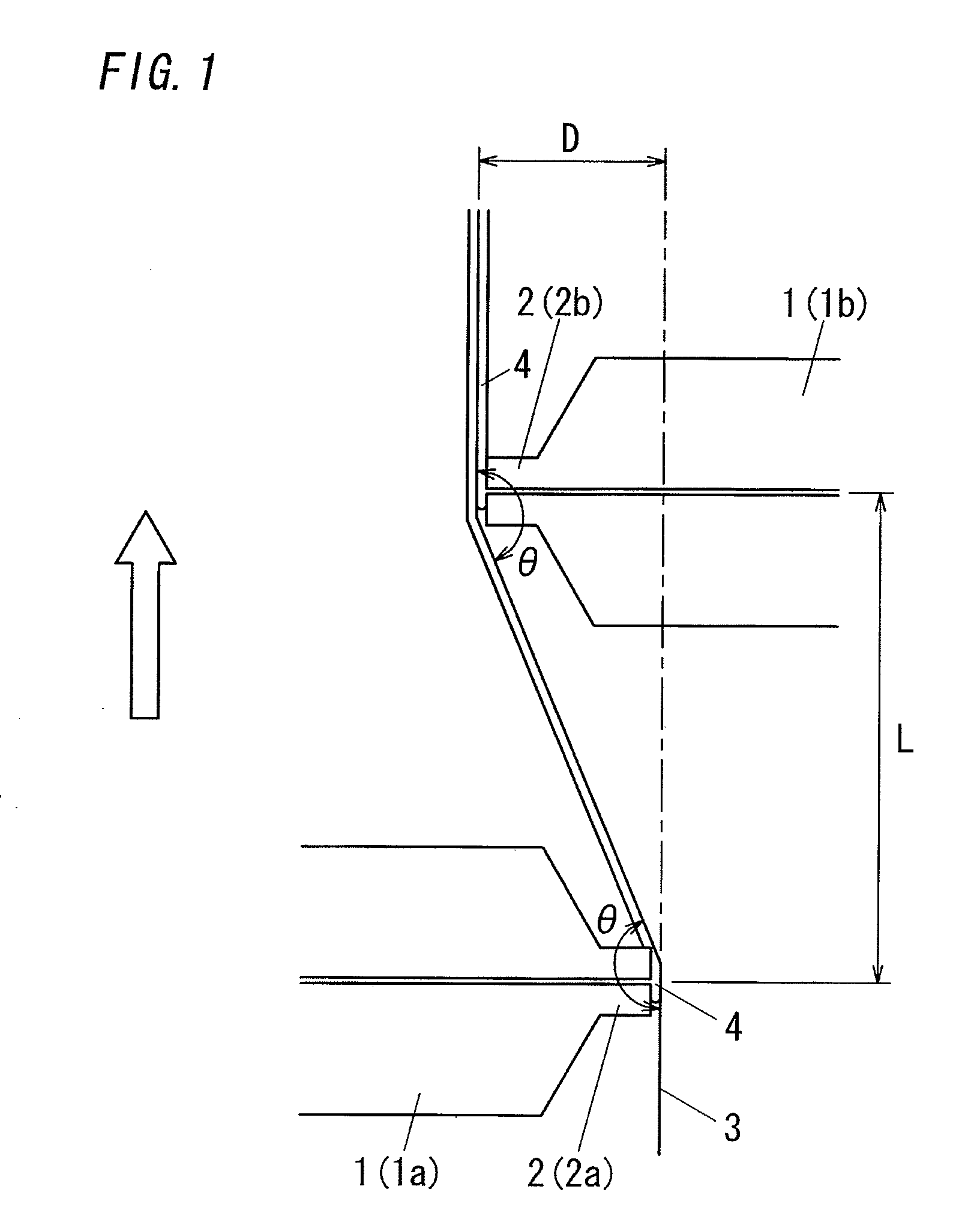
[0027]FIG. 1 shows an instance corresponding to a process and a device of fabricating a prepreg for a printed circuit board of the present invention. The device of fabricating a prepreg for a printed circuit board includes a first dispenser 1a and a second dispenser 1b each of which is a die coater. A substrate sheet 3 is fed along a direction of an illustrated arrow (a direction from lower to upper) in such a manner to pass between the two die coaters, and is coated with a resin fluid at its opposite surfaces one-by-one. Besides, in the present embodiment, the first dispenser 1a and the second dispenser 1b are die coaters of the same type, but may be die coaters of different types.

[0028]Each of the first dispenser 1a and the second dispenser 1b has a coating head 2. The coating head 2 extends in a width direction of the substrate sheet 3 for pressed contact with the substrate sheet 3 along its entire width and is formed with a spout extending in the width direction of the substrate...

second embodiment

[0043]In the first embodiment, the explanation is made to the instance employing die coaters as the first dispenser 1a and the second dispenser 1b. In the present embodiment, the explanation is made to the instance employing roll coaters as the first dispenser 1a and the second dispenser 1b.

[0044]FIG. 3 shows a primary part of the process and the device of fabricating a prepreg for a printed circuit board on the present embodiment. In the present embodiment, the process employs the first dispenser 1a and the second dispenser 1b each of which is in the form of a roller defining therearound a coating head 2 which is held in pressed contact with the substrate sheet 3 for transferring the resin fluid 4 from the periphery of the roller to the surface of the substrate sheet 3 as the roller rotates. The first coating head 2a and the second coating head 2b are arranged to be spaced from each other by the distance L between dispensers in the feeding direction of the substrate sheet 3. The f...

examples

[0047]Evaluation was made to prepregs respectively fabricated under plural conditions shown in table 1 by use of the prepreg fabricating device including the two dispensers 1 configured to perform resin-coating on the opposite surfaces of the substrate sheet 3 respectively. That is, the prepregs ware fabricated by coating the substrate sheet 3 with the resin fluid 4 under the plural conditions shown in the table 1: kind of the dispenser 1, the distance L between dispensers, the distance D between overlapped heads, the feeding speed of the substrate sheet 3, the line tension of feeding the substrate sheet 3, and the ratio by weight per unit time of the injection amount of the first dispenser 1a to the injection amount of the second dispenser 1b. With regard to each prepreg, impregnation of the resin fluid 4 was evaluated and a ratio of thicknesses of resin layers of a prepreg was measured. Further, quality of a prepreg for a printed circuit board was checked based on comprehensive ev...


PUM

PropertyMeasurementUnit
Timeaaaaaaaaaa
Speedaaaaaaaaaa
Speedaaaaaaaaaa

Abstract

The present invention has been aimed to propose a process and a device of fabricating a prepreg for a printed circuit board which are capable of controlling respective thicknesses of resin layers on the opposite surfaces of a resultant prepreg, removing air bubbles from the resultant prepreg, and improving productivity.The present invention is a process of resin-coating the opposite surfaces of an elongated substrate sheet 3. The process includes the steps of: feeding the substrate sheet 3 while tensioning the same in a feeding direction along the length of the substrate sheet 3; coating, by the coating head 2 of the first dispenser 1a, one surface of the substrate sheet 3 with the fluid resin 4 while pressing against the one surface to bend the substrate sheet 3; and subsequently coating, by the coating head 2 of the second dispenser 1b, the other surface of the substrate sheet 3 with the fluid resin 4 while pressing against the other surface to bend the substrate sheet 3. A die coater and a roll coater can be used as the first dispenser 1a and the second dispenser 1b.

Description

TECHNICAL FIELD[0001]The present invention relates to a process of fabricating a prepreg for a printed circuit board by coating a substrate sheet made of glass fibers or the like with a resin fluid, and a device of fabricating a prepreg for a printed circuit board comprising equipment of coating a substrate sheet with a resin fluid.BACKGROUND ART[0002]In the past, a dip and squeeze coating process and a dip and comma knife coating process are well known as a process of fabricating a prepreg for a printed circuit board. Each of these processes includes steps of: impregnating a substrate sheet with a resin fluid obtained by dissolving an insulating resin; subsequently drying it to a semi-cured state; and scraping away an excess resin on a surface of the substrate sheet in order to adjust a thickness of a resin layer of a resultant prepreg. Accordingly, these processes can feed the substrate sheet at appropriate speed, and thereby fabricate a prepreg efficiently and continuously. Howev...

Claims


Application Information

Patent Timeline
IPC IPC(8): B05D3/12B05C11/02B05C11/00
CPCH05K1/0366H05K2201/029H05K2203/1572H05K2203/1545H05K2203/0759C08J5/24B29B11/06
Inventor MATSUZAKI, YOSHINORIFUJITA, KAZUHIKOTASHIRO, MASAYAKOBAYASHI, SHINYA
Owner PANASONIC INTELLECTUAL PROPERTY MANAGEMENT CO LTD
Learn More