Anti-Splash Holding Tank and Stand-Alone Anti-Splash Guard for Portable Toilets

a portable toilet and anti-splash technology, applied in the field of portable toilets and restrooms, can solve the problems of serious infections, unsanitary for users, and insufficient portability of non-flushing toilets, and achieve the effects of low material and manufacturing costs, and positive buoyancy in water

Inactive Publication Date: 2015-10-29
LIKEWISE KIMBERLY +1
View PDF0 Cites 1 Cited by
  • Summary
  • Abstract
  • Description
  • Claims
  • Application Information

AI Technical Summary

Benefits of technology

[0005]The embodiments of the instant innovation comprise a substantially sloped anti-splash guard that is located at the bottom of a non-flush portable toilet holding tank directly under the seat, immersed below the water level in the tank. In the preferred embodiment of the instant innovation, the anti-splash guard is conically shaped, and integrally formed with a portable toiled holding tank to form a permanent raised portion directly under the seat that is manufactured in place with the holding tank. In other embodiments, the invention is a stand-alone conical or pyramidal insert that may be retrofitted into existing portable toilet holding tanks. In the preferred embodiment, a portable toilet holding tank may be manufactured by injection or rotational molding techniques, where the mold is machined to include a conical / pyramidal guard of specific dimensions directly under the opening of the toilet seat. In this manner, the inventive anti-splash guard is formed integrally with the holding tank.
[0006]In stand-alone embodiments of the invention for retrofitting purposes, tapered pillar inserts having conical or pyramidal shapes of specific dimensions may be formed by injection and rotational molding polymers such as high-density polyethylene. The anti-splash guard inserts may be hollow or solid, although the former embodiment may be preferable due to lower costs of materials and manufacture. While the latter embodiment is heavier than the former, but both embodiments may be positively buoyant in water if made from most common plastics, and tend to float if not affixed to the bottom of the holding tank. In addition to the conical or pyramidal shape, a mounting flange or rim may be integrally formed around the base of the structure. The inventive anti-splash inserts may be affixed to the bottom of the holding tank by a variety of means, including, but not limited to, adhesives, suction cups, weights and fastening means such as bolts. The inserts may also be made from light corrosion-resistant metals such as aluminum, brass or copper, which would have negative buoyancy in water and tend to stay at the bottom without the aid of a fixation means. However, to prevent the inventive guard insert from moving laterally away from the position of highest effectiveness, that is, directly under the seat opening of the holding tank, a fixation means may be necessary.

Problems solved by technology

A problem is generally encountered by users of these facilities when accessing the toilet, as deposition of solid or liquid matter into the tank frequently causes holding tank water to splash upwards, contacting the user while sitting down on the seat.
This situation is highly unsanitary for the user, as pathogens of many kinds can contact the user's skin and orifices, potentially causing serious infections.
This problem is particularly acute in portable toilets where the water holds accumulated waste by many users, and not flushed away and replenished with clean water, as is done in a flush toilet after each use.
While previously disclosed devices may work well for flush toilets, they may prove inadequate for portable non-flush toilets as they generally rely on the fact that the bowl of the flush toilet will be evacuated by flushing after each use, and in general would not tolerate accumulation of solid matter.

Method used


Image

  • Anti-Splash Holding Tank and Stand-Alone Anti-Splash Guard for Portable Toilets
  • Anti-Splash Holding Tank and Stand-Alone Anti-Splash Guard for Portable Toilets
  • Anti-Splash Holding Tank and Stand-Alone Anti-Splash Guard for Portable Toilets

Examples


Embodiment Construction

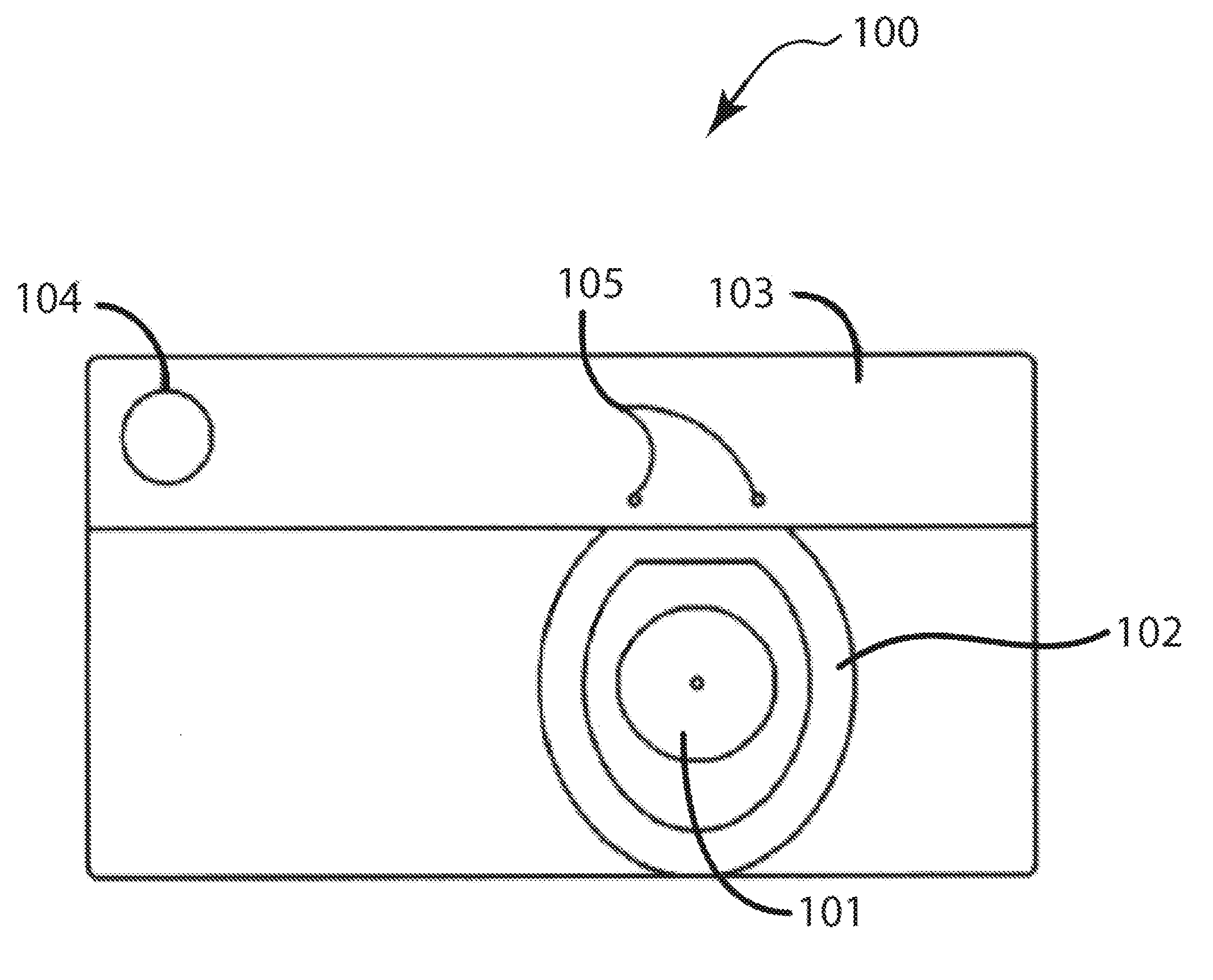
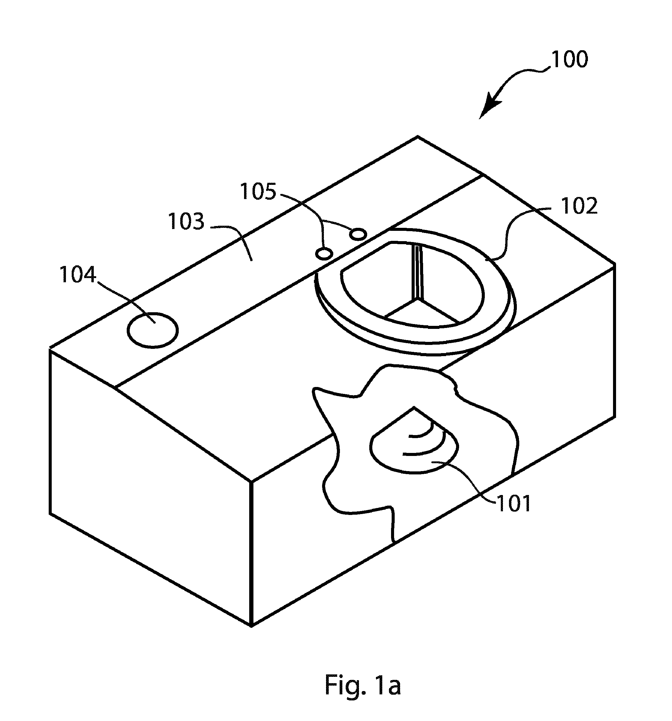
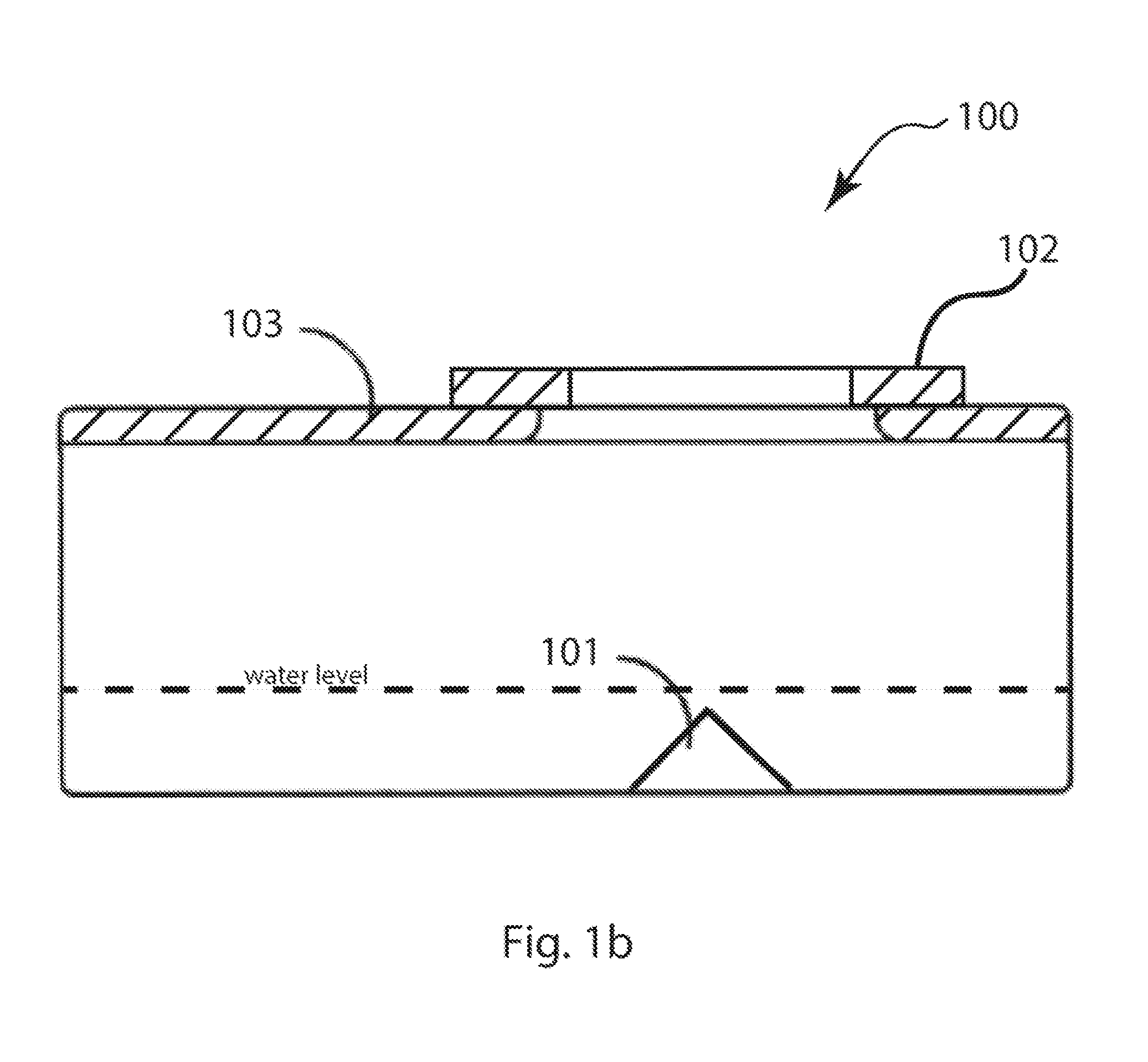
[0019]FIG. 1a shows an isometric view of the preferred embodiment of the invention, a portable toilet holding tank 100 having a tapered pillar anti-splash guard 101 having sloped sides converging to an apex, where in the embodiment shown, the tapered pillar is a cone, shown in the cut-away view rising up from the bottom of the tank directly under the seat 102 integral with tank body 103. Other conical shapes may be used as tapered pillars, where the shape may be substantially conical. In the preferred embodiment, anti-splash guard 101 projects upward from the bottom of holding tank 100, whereby the height of its apex may be a small fraction of the total height of tank 100, in order to remain submersed below the water surface. However, a taller embodiment of anti-splash guard 101 may extend above the water surface so as to expose the apex. Also shown in FIG. 1a are vent hole 104 and seat mounting holes 105. The surface of the water or portable toilet fluid, such as those commercially...


PUM


Abstract

Described herein is an inventive anti-splash guard for non-flush portable toilets. The innovation comprises a sloped structure either affixed to or made integral with the bottom of the holding tank of a portable toilet, positioned under the seat. The form of the inventive anti-splash guard is preferably conical, but may also be pyramidal, hemispherical and ellipsoidal. Functionally, the innovation may be submerged fully under the level of the holding tank water, so that the impact of deposited solid matter is absorbed by the anti-splash guard and not transferred to the surrounding water. In this way the upward splash of the water is suppressed, and risk of contamination to the user is greatly reduced. The disclosure describes both a portable toilet holding tank with an integrally formed anti-splash guard according to the invention, and stand-alone embodiments that may be retrofitted to existing portable toilets.

Description

CROSS REFERENCE TO PRIORITY APPLICATIONS[0001]This non-provisional utility patent application claims the benefit of U.S. Provisional Application No. 61 / 982,874, filed on Apr. 23, 2014.FIELD OF THE INVENTION[0002]This invention relates to anti-splash devices for toilets, in particular portable toilets and restrooms.BACKGROUND[0003]Portable toilets are necessary to dispose of liquid and solid waste from human beings when normal toilet facilities are not available. Examples are construction sites, concerts, sporting events, and the like. When portable toilets are delivered for use, the holding tank is filled with a few inches of water containing sanitation chemicals. A problem is generally encountered by users of these facilities when accessing the toilet, as deposition of solid or liquid matter into the tank frequently causes holding tank water to splash upwards, contacting the user while sitting down on the seat. Current designs of holding tanks for portable toilet are all flat-botto...

Claims


Application Information

Patent Timeline
Patent Type & Authority Applications(United States)
IPC IPC(8): A47K11/04A47K17/00E04H1/12
CPCA47K11/04A47K17/00E04H1/1216E03D7/00A47K11/035B61D35/007E03D9/00
Inventor LIKEWISE, KIMBERLYLIKEWISE, MICHAEL R.
Owner LIKEWISE KIMBERLY
Why Eureka
Try Eureka