
Method and apparatus for subsea installations

a technology for subsea installations and methods, applied in the direction of artificial islands, marine vessel transportation, fluid removal, etc., can solve the problems of reducing the effective crane capacity, and reducing the weight and size of the load, so as to facilitate the lateral control of the apparatus

Inactive Publication Date: 2015-03-31
SUS DEPLOYMENT SYST
View PDF25 Cites 9 Cited by
  • Summary
  • Abstract
  • Description
  • Claims
  • Application Information

AI Technical Summary

Benefits of technology

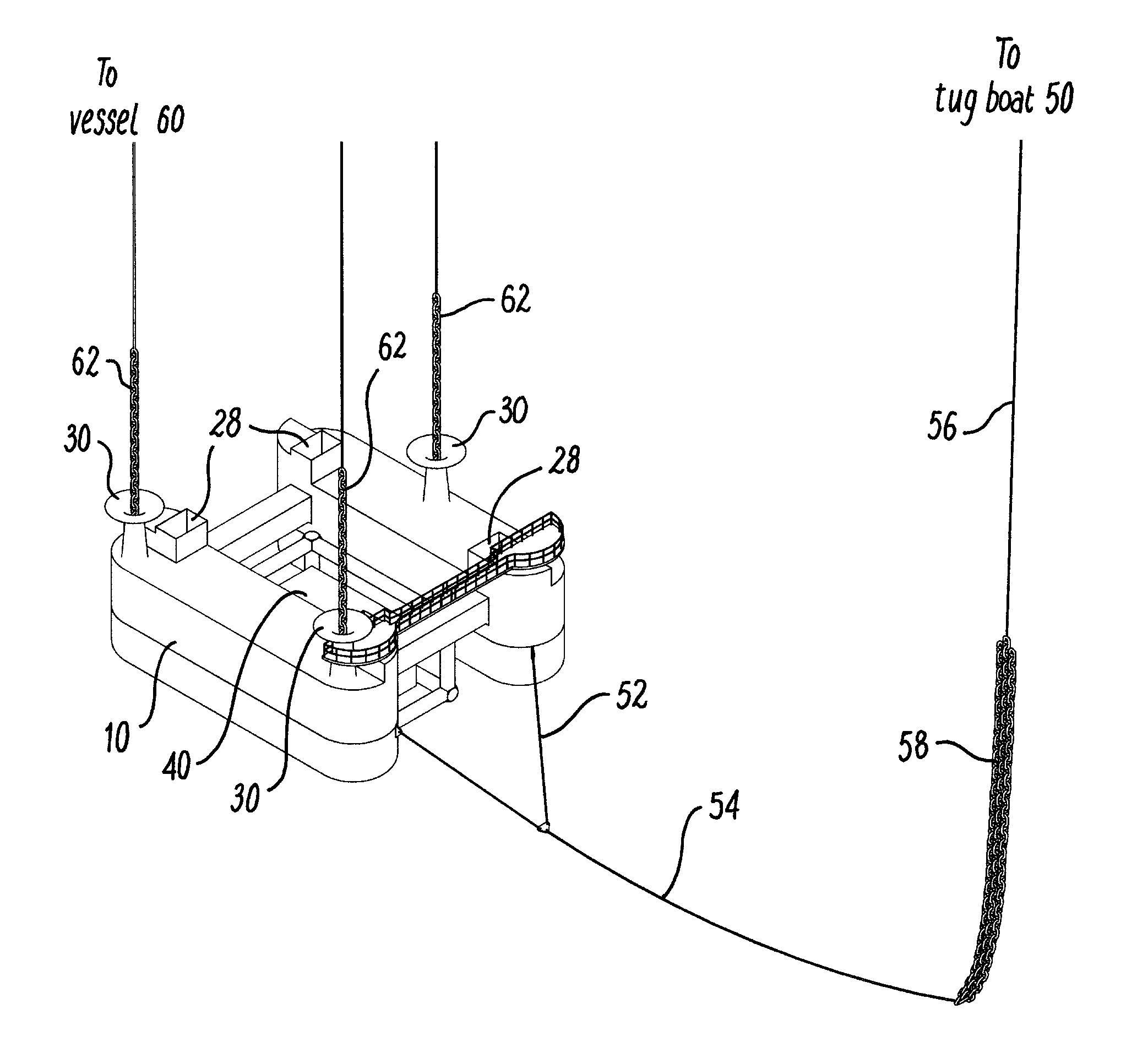
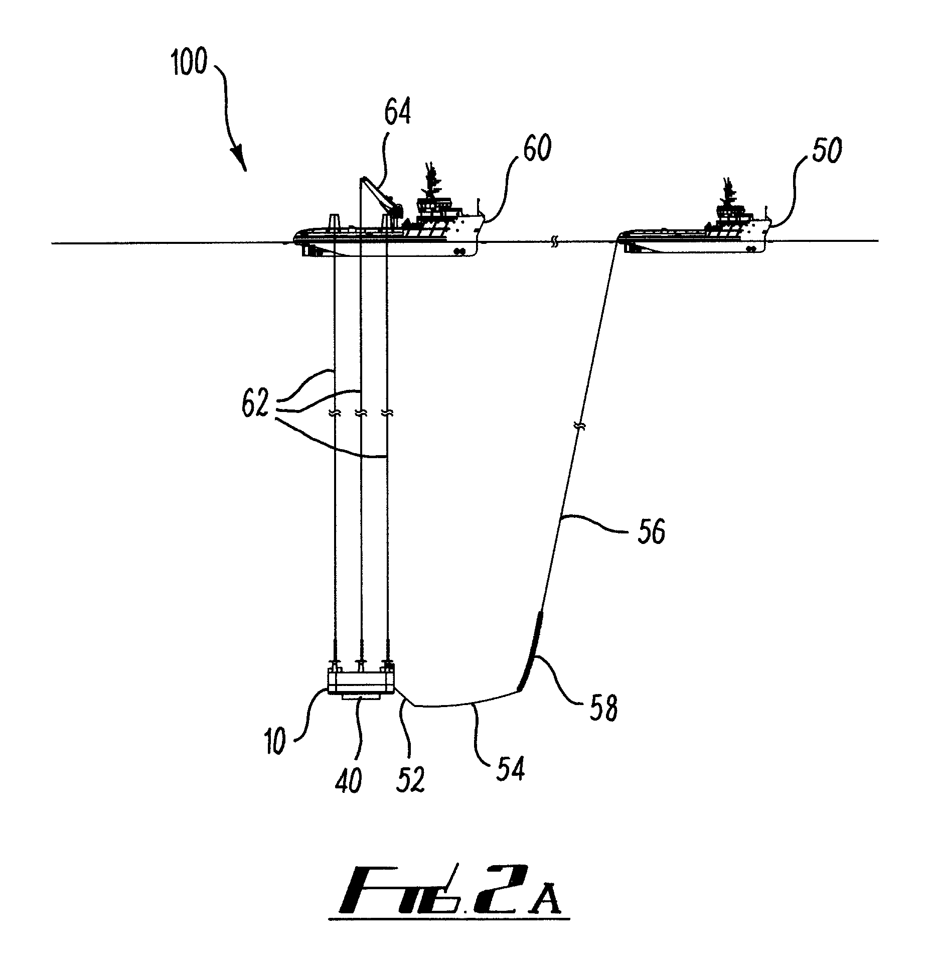
[0017]According to a first aspect of the invention, there is provided a method of lowering a load to a bed of a body of water, the method comprising:Forming an assembly from a buoyancy apparatus and a payload, wherein the buoyancy apparatus renders the assembly positively buoyant;Submerging the assembly to a position at a first height above the bed;Deploying a control weight from a vessel to the assembly to overcome the positive buoyancy of the assembly and thereby lower the payload from the first height to the bed.
[0027]The apparatus may comprise a clump weight line. The control weight may be a control chain, and the receptacle may comprise a lower surface for supporting a first portion of the control chain. Preferably the receptacle is configured for suspension of a second portion of the control chain above the first portion within the receptacle. This facilitates lateral control of the apparatus in a submerged state. The receptacle may comprise an elongate tower oriented substantially vertically on the buoyancy apparatus.

Problems solved by technology

Manifolds and other items of infrastructure have a significant weight and size which introduce complications to the installation process.
For example, the weight and size of the load is inherently limited by the capacity and reach of the crane.
In addition, where installation is required in deep water, the weight of the crane wire contributes significantly to the load on the crane, which reduces the effective crane capacity.
Although the effects of crane wire weight can be eliminated by using weight neutral crane wires, these have the disadvantage that they contribute to the complexity of the operation and may add to the duration of the installation process.
During the lifting process, dynamic and hydrodynamic loading on the vessel can be significant, which also requires a reduction in the effective crane capacity.
This type of installation method also exposes the apparatus being lifted to wave slamming as the load passes through the splash zone and water surface.
Many items of subsea infrastructure comprise sensitive equipment which may be exposed to risk of damage from wave action.
In addition, weather limitations may be imposed to avoid exposure of the load to large accelerating or decelerating forces during pick-up or landing on the seabed or deck of a vessel which may cause damage to the equipment.
To address this, many cranes are provided with active heave compensation systems that will allow the soft landing of loads, but such active heave compensation systems can be deficient when used in deep water operations.
However, an HLV requires multi-reeved crane blocks with slow hoisting and lowering speeds.
The payloads are lowered or lifted very slowly, which increases the time during which the equipment is exposed to risk of damage at or near the water surface.
The problems described above are affected by sea state, with adverse environmental conditions further reducing the crane capacity and the time in which the marine vessel is able to work.
Increasing sea state also increases the risk of damage to the load.
Failure of the lifting system is potentially catastrophic to the load and may endanger the marine vessel and / or its crew.
In addition, the point from which the load is suspended is usually close to mid-ships, and is therefore subject to lower dynamics due to the pitch and roll of the vessel.
However, the operation remains highly weather sensitive, due to the suspension of the load directly beneath the vessel throughout the transportation phase.
The process also has the disadvantage that the additional inshore lift suspension operation is required.
However, the W-suspension method has the disadvantage that it requires buoyancy tanks, which must be integral with the payload or temporally coupled to it.
Where integral buoyancy tanks are provided, the structure becomes larger and heavier.
The buoyancy tanks are subject to hydrostatic loading which limits the depth to which the method can be used.
The lateral position of the structure during final lowering can be difficult to control via the clump weights, particularly in areas with strong currents.
Finally, in the W-suspension system, failure of the buoyancy tanks is catastrophic to the load.
The requirement for a winch is a disadvantage, as it adds to the weight and complexity of the vessel.
Failure of the winch system or buoyancy tanks is catastrophic to the operation.
This system suffers from the drawback that the length between the buoyancy and the bottom of the load must exceed that of the clump weight if the load is to be landed.
This also means that there is no provision for parking the system; the load must be lowered on to the seabed if the operation is to be interrupted.
However, the arrangement of U.S. Pat. No. 4,828,430 relies on an integral buoyancy tank in the load, which adds to the size and weight.
The installation method also requires a crane for the initial lift phase from the deck of the vessel to the body of the water, and is subject to the limitations of the conventional surface transport method described above.

Method used


Image

  • Method and apparatus for subsea installations
  • Method and apparatus for subsea installations
  • Method and apparatus for subsea installations

Examples


Embodiment Construction

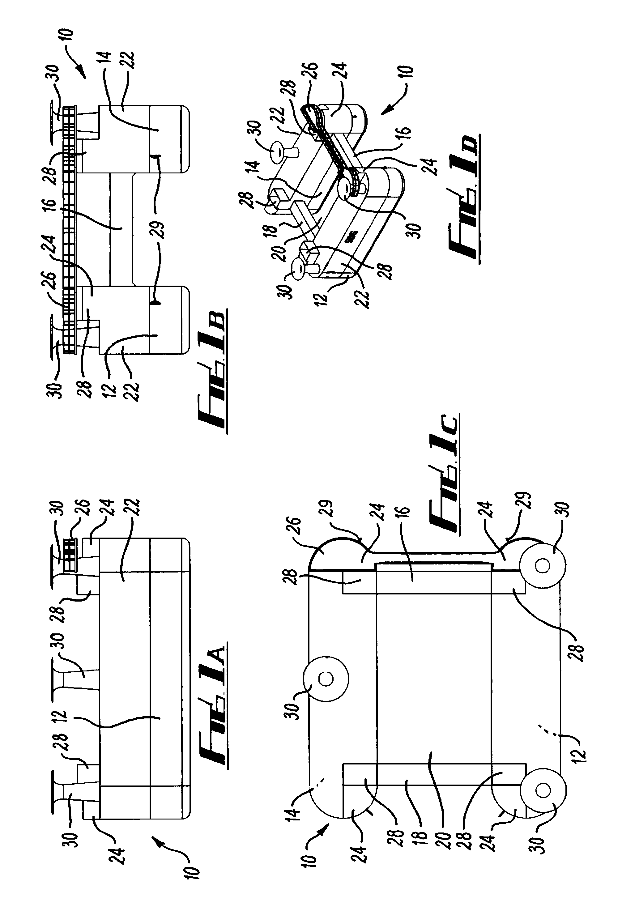
[0053]Referring firstly to FIGS. 1A to 1D, there is shown an apparatus 10 used in an installation operation for lowering or raising a payload or structure to or from the bed of a body of water. In the examples described, the invention is applied to a marine environment in which the load is lowered or and / or raised from the seabed. It will be appreciated that the invention also has application to freshwater environments.

[0054]The apparatus 10 comprises two hulls or pontoons 12 and 14, which are of a size and shape suitable for providing enough buoyancy for transportation of the apparatus with shallow draught. The hulls 12, 14 are linked together by one forward transverse bridging member 16 and one aft transverse bridging member 18, which maintain the hulls in a fixed spatial relationship and provide a load bearing structure for a payload (not shown). A space 20 is defined between the hulls. The spacing between the hulls 12, 14 is selected to accommodate a payload or structure to be l...


PUM


Abstract

There is provided a method and apparatus for lowering and / or raising a load or structure to or from the bed of a body of water. The apparatus comprises a buoyancy apparatus configured to be coupled to a load, and having positive buoyancy sufficient to lift the load. At least one receptacle is provided on the apparatus for receiving a control weight lowered from a vessel to lower or raise the assembly. The lowering method includes forming an assembly from a buoyancy apparatus and a load and submerging the assembly to a position at a first height above the bed. In a preferred embodiment the assembly is submerged by a clump weight tow system. A control weight is deployed from a vessel to the assembly to overcome the positive buoyancy of the assembly and thereby lower the load from the first height to the bed. The raising method reverses the steps of the lowering method.

Description

[0001]The present invention relates to methods and apparatus for use in the installation of structures or loads on to the bed of a body of water. Aspects of the invention relate to a method and apparatus for lowering a load to the bed of a body of water. Other aspects of the invention relate to a method of recovering a load from the bed of a body of water.BACKGROUND TO THE INVENTION[0002]Industries such as the offshore oil and gas exploration and production industry or the marine renewable energy industry require subsea infrastructure and facilities to support the offshore operations, including for example manifolds, trees, riser arches, seabed foundations and pipelines. One example of an item of infrastructure is a subsea manifold, which provides an interface between pipelines and wells at the seabed. A manifold may be designed to handle flow of produced hydrocarbons from multiple wells and direct the flow to several production flow lines. A typical manifold will comprise flow mete...

Claims


Application Information

Patent Timeline
Patent Type & Authority Patents(United States)
IPC IPC(8): E02D23/02B63B27/00B63C11/00E21B19/00E21B41/00E21B41/04
CPCE21B19/002B63B27/00B63C11/00E21B41/0007E21B41/04B63B35/00E02B17/00E21B43/01B63B35/40B63B2035/448E02B17/02E02B2017/0039
Inventor JOENSEN, ARNBJORNPAUL, SAMUEL DAVID IRVINE
Owner SUS DEPLOYMENT SYST
Learn More