Downhole Apparatus and Method

Inactive Publication Date: 2015-10-29
WEATHERFORD TECH HLDG LLC
View PDF8 Cites 3 Cited by
  • Summary
  • Abstract
  • Description
  • Claims
  • Application Information

AI Technical Summary

Benefits of technology

[0037]In use, the tubular body and the bore member or sleeve may together define a downhole tool for performing or permitting a borehole operation to be carried out. The apparatus may be moveable from a first configuration to a second configuration. The first configuration may comprise a run-in configuration. The second configuration may comprise an activated

Problems solved by technology

While the provision of larger contact surface areas provide a number of benefits, in the high temperature and high pressure environment of some oil and gas well boreholes, conventional arrangements suffer from the drawback that forces between the ball and the seat may be sufficient to cause the ball to become swaged or otherwise

Method used


Image

  • Downhole Apparatus and Method
  • Downhole Apparatus and Method
  • Downhole Apparatus and Method

Examples


Example

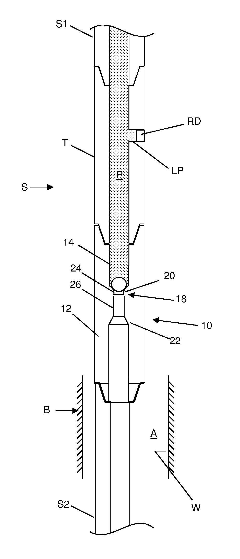
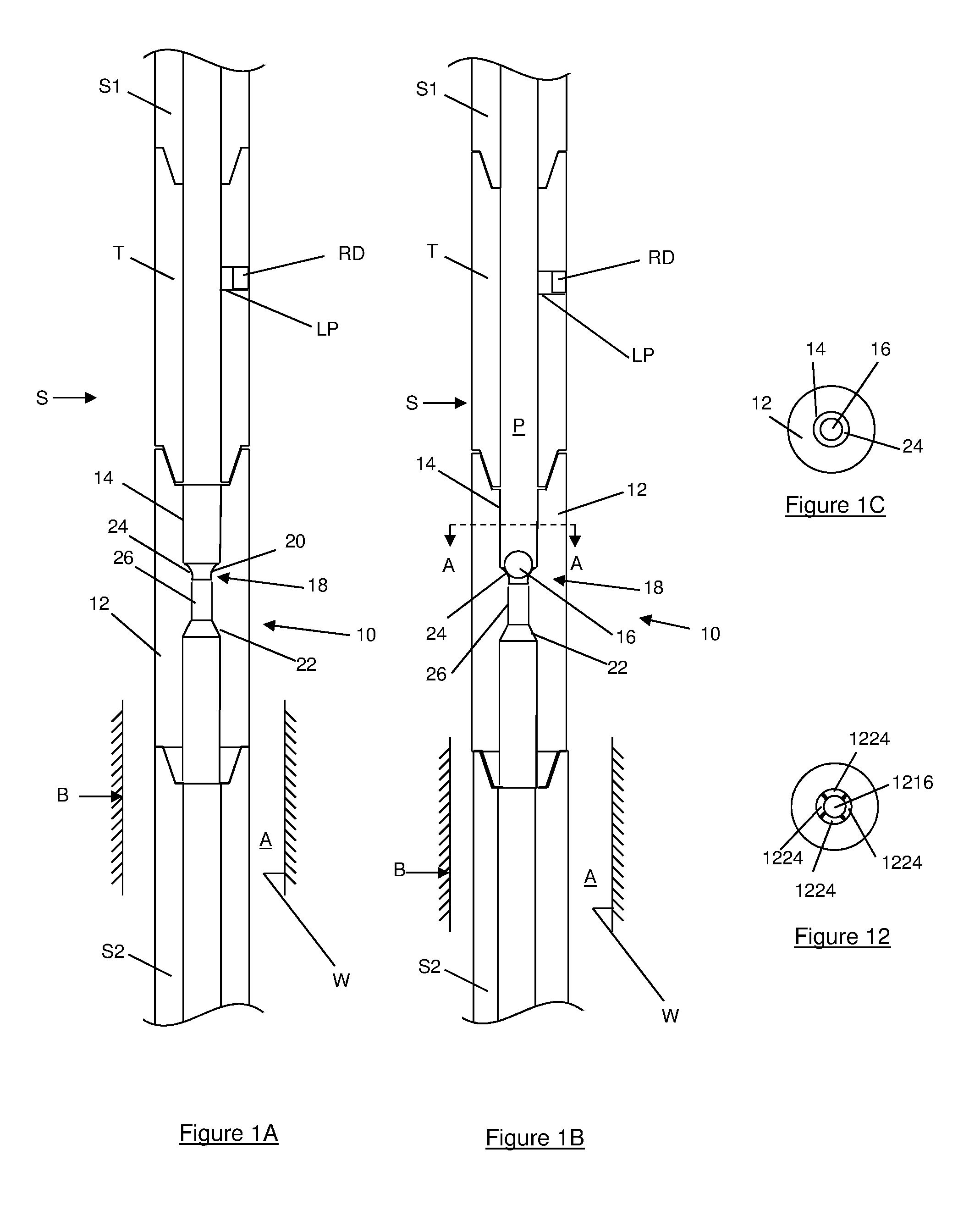
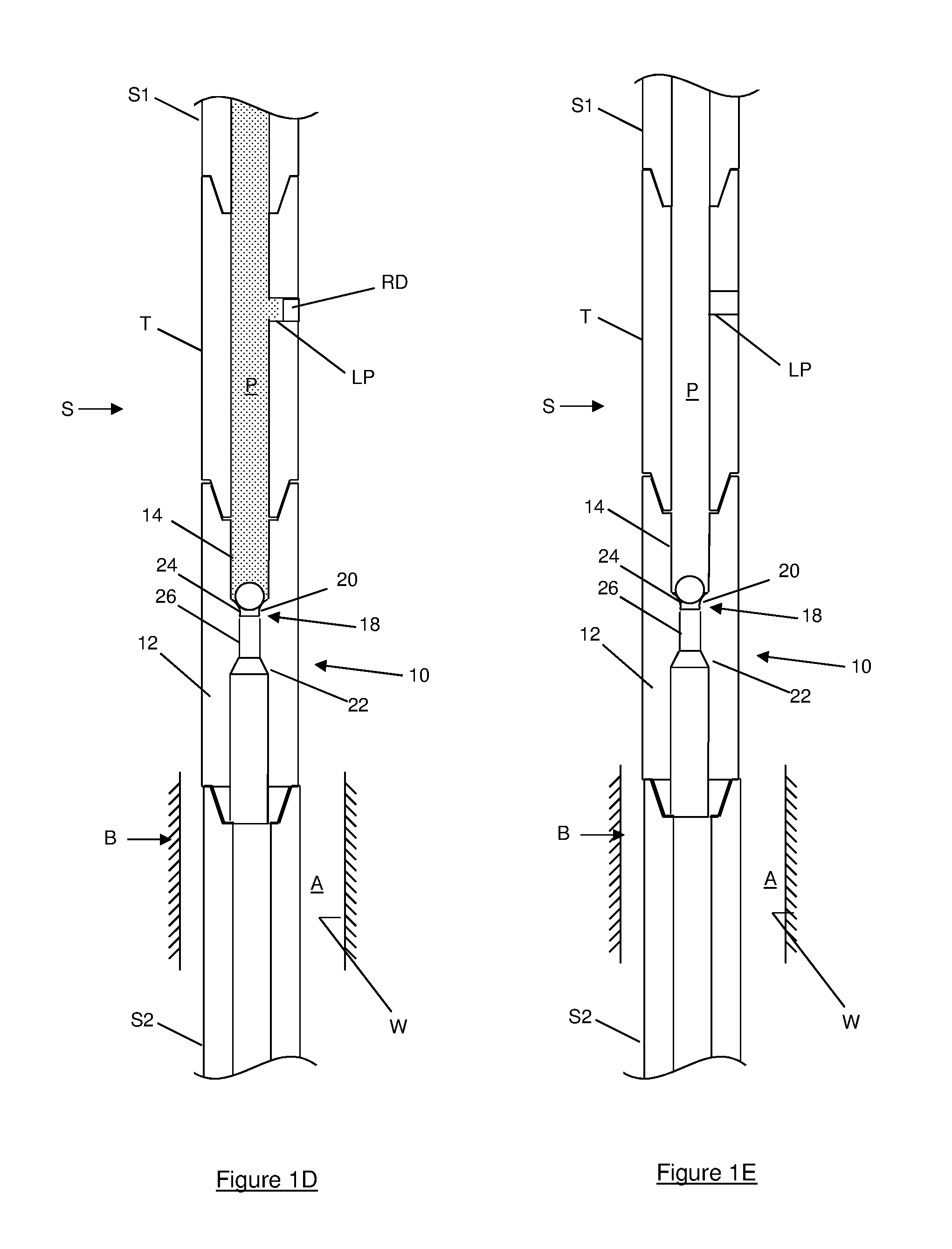
[0107]In this first embodiment, the apparatus 10 is configured so that the engagement between the ball 16 and the seat 18 seals or at least restricts fluid passage downstream of the seat 18 to increase upstream fluid pressure P, the increased upstream fluid pressure P being used to perform or permit a borehole operation to be carried out by activating the tool T. By way of example, the increased upstream pressure may exceed a threshold value required to burst the rupture disk(s) RD in the tool T to permit fluid communication between the throughbore 14 and annulus A disposed between the apparatus 10 and the wall W of the borehole B.

[0108]In use, the convex object engaging surface 24 provides an opposing, rather than complementary or matching, engaging surface for landing the ball 16 and provides a reduced or minimal contact surface, preferably a line or point contact, between the ball 16 and the seat 18, thereby preventing or at least mitigating the possibility of the ball 16 becomin...

Example

[0118]The apparatus 410 is similar to the second embodiment shown in FIGS. 2A to 2C, the difference being that apparatus sleeve 428 is coupled to a downhole tool T. In the illustrated embodiment, the downhole tool T comprises a sleeve 40. The downhole tool T is disposed downstream or downhole of the seat 418 and, in use, the ball 416 is dropped, pumped or otherwise motivated through the string S and into the bore 414 of the tubular body 412 until it lands on the seat 418, as shown in FIG. 4B. In this fourth embodiment, the apparatus 410 is configured so that engagement between the ball 416 and the seat 418 seals or at least restricts fluid passage through the tubular body 412 to provide a fluid pressure differential PD across the seat 418, the fluid pressure differential PD being utilised to perform or permit a borehole operation to be carried out, in this embodiment shear the shear pin 430 and move the sleeve 428 and sleeve 40 relative to the tubular body 412 from the position show...


PUM


Abstract

A downhole apparatus (10) for use in activating a downhole tool (T). The apparatus (10) comprises a seat (18) configured to receive an object, such as a ball (16). The seat (18) comprises a convex object engaging surface (24) for engaging the object.

Description

FIELD OF THE INVENTION[0001]This invention relates to a downhole apparatus and method. More particularly, but not exclusively, embodiments of this invention relate to a seat for receiving an object, such as a ball.BACKGROUND TO THE INVENTION[0002]In the oil and gas exploration and production industry, well boreholes are drilled in order to access subsurface hydrocarbon-bearing formations. A tubular string, such as a completion string or running string, may be made up and run into the borehole and operated to perform a number of different operations in the borehole. Some operations to be carried out may require that one or more tools be activated from a run-in configuration to an activated configuration.[0003]A variety of activation mechanisms may be used. One or more tool may be mechanically activated, for example by applying a force from surface or by running a mechanical activation or setting tool into the bore and applying a force to the tool using the setting tool. Alternatively...

Claims


Application Information

Patent Timeline
IPC IPC(8): E21B34/12E21B33/12
CPCE21B34/12E21B2034/007E21B33/12E21B23/04E21B34/14E21B23/08E21B34/10E21B2200/06E21B34/142
Inventor PATTON, DAMIEN GERARDWEBSTER, OLIVERPURKIS, DANIEL GEORGE
Owner WEATHERFORD TECH HLDG LLC
Why Eureka
Try Eureka