Retaining ring retention system and method

a technology of retaining rings and rings, applied in the direction of mechanical equipment, manufacturing tools, washing machines, etc., can solve the problems of speed exceeding by accident or necessity

Active Publication Date: 2015-10-29
VOLVO LASTVAGNAR AB
View PDF8 Cites 40 Cited by
  • Summary
  • Abstract
  • Description
  • Claims
  • Application Information

AI Technical Summary

Benefits of technology

[0005]According to one embodiment of the present invention, a retained member configured to prevent centrifugal force from disassociating a retaining ring provided with lugs from a groove located on a rotatable shaft when securing the retained member to the rotatable shaft and rotating with the shaft includes a substantially annular portion and a retention lip provided with a cutout portion. The annular portion defines an opening sized to receive the rotatable shaft so that the retained member is rotatable with the shaft. The cutout portion is configured to accommodate the lugs when in an installing position as the retained member is snap fit into the groove. The retention lip is configured to circumscribe the lugs when the lugs are rotated relative to the installing position into an installed position and in the groove to prevent the lugs from being forced apart by the centrifugal force such that the retaining ring could disassociate from the groove.
[0006]According to another embodiment of the present invention, a method for providing a retained member configured to prevent centrifugal force from disassociating a retaining ring provided with lugs from a groove located on a rotatable shaft when securing the retained member to the rotatable shaft and rotating with the shaft includes the step of providing a retained member that includes a substantially annular portion that defines an opening and a retention lip that includes a cutout portion, wherein the opening is sized to receive the rotatable shaft so that the retained member is rotatable with the shaft, the cutout portion is configured to accommodate the lugs when in an installing position as the retained member is snap fit into the groove, and the retention lip is configured to circumscribe the lugs when the lugs are rotated relative to the installing posting into an installed position and in the groove to prevent the lugs from being forced apart by the centrifugal force such that the retaining ring may disassociate from the groove.
[0008]According to still yet another embodiment of the present invention, a method for installing a retaining ring and a retained member on a rotatable shaft provided with a groove includes the steps of providing the retaining ring that includes lugs provided with an installed position and an installing position, wherein a distance between the lugs is greater when in the installing position than in the installed position, providing a retained member that is provided with a retention lip that is adapted to circumscribe the lugs when in the installed position so that the retention lip prevents the lugs from being forced apart by centrifugal force such that the retaining ring may disassociate from the groove and includes a cutout portion that accommodates the lugs when in the installing position, installing the retained member around the rotatable shaft so that the retained member is rotatable with the rotatable shaft, positioning the lugs of the retaining ring within the cutout portion of the retained member and forcing the lugs apart to provide the lugs with the installing position, snap fitting the retaining ring in the groove so that the retaining ring is rotatable with the rotatable shaft and the retaining ring secures the retained member to the rotatable shaft, and rotating the retaining ring relative to the installing position to provide the installed position, whereat the retention lip circumscribes the lugs so that the retention lip prevents the lugs from being forced apart by centrifugal force such that the retaining ring may disassociate from the groove.

Problems solved by technology

Although manufacturers of retaining rings typically publish maximum speeds for retaining rings, sometimes these speeds are exceed by accident or necessity.

Method used


Image

  • Retaining ring retention system and method
  • Retaining ring retention system and method
  • Retaining ring retention system and method

Examples


Embodiment Construction

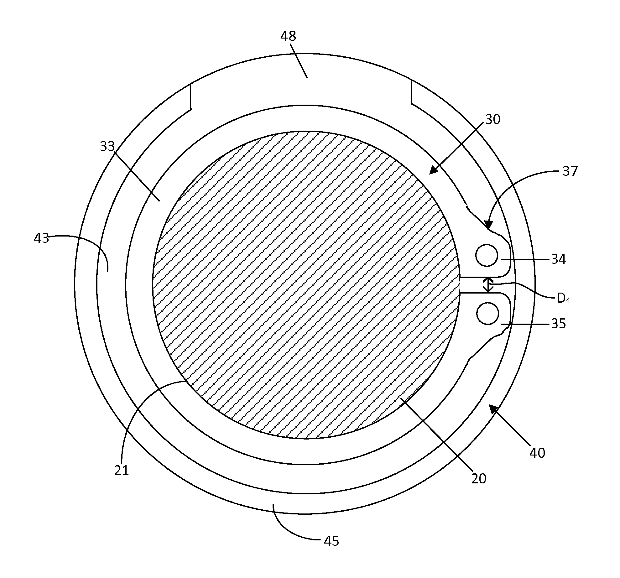
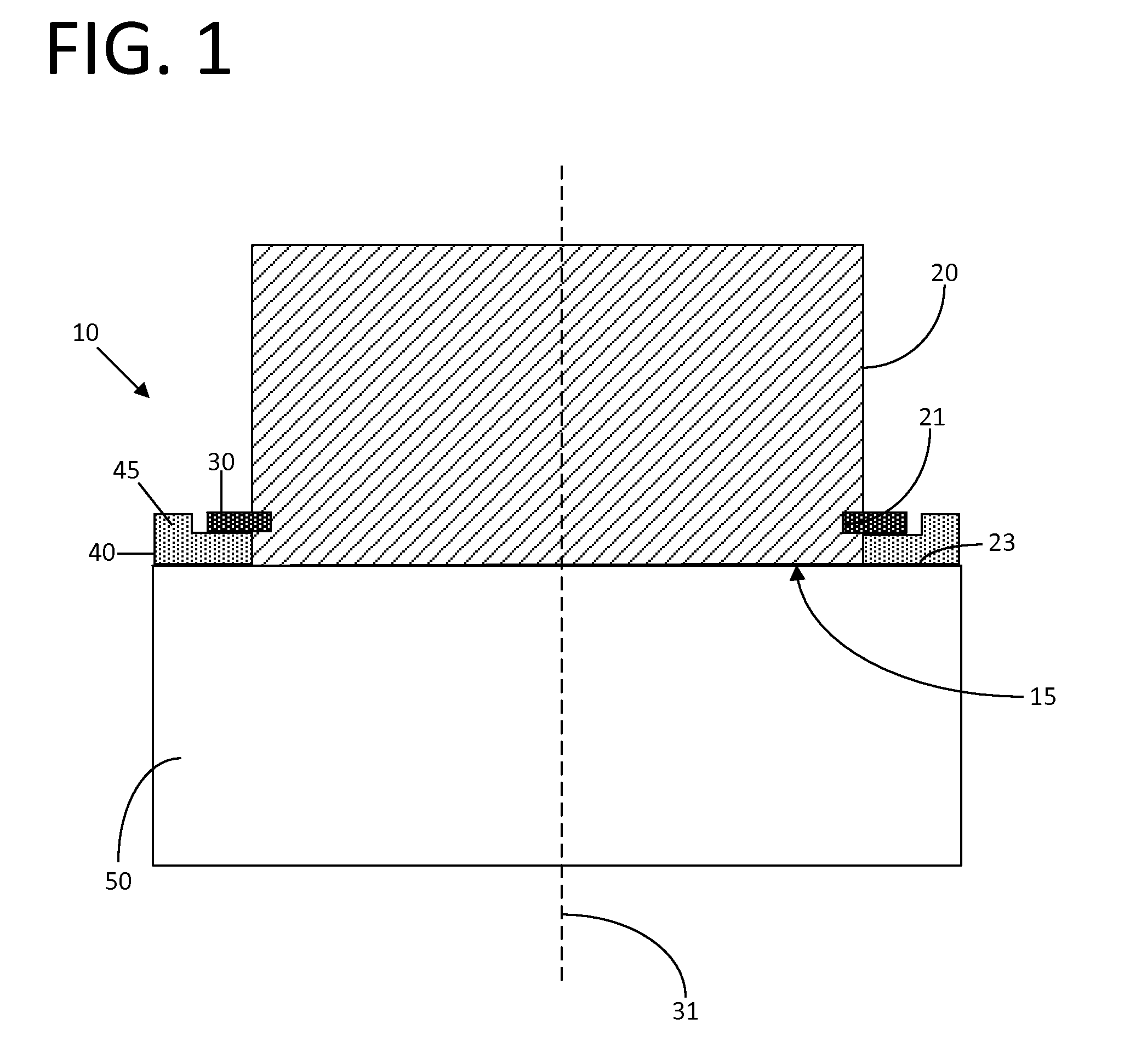
[0016]FIG. 1 depicts an embodiment of a retaining ring retention system 10 provided with a rotatable shaft 20 that includes a groove 21, a retaining ring 30, and a retained member 40. In the presently preferred embodiment the rotatable shaft 20 is a component of a vehicle powertrain 15 and the retained member 40 is a thrust washer; however those of ordinary skill in the art will appreciate that it is within the scope of the present embodiment to employ the principals of the present embodiment in conjunction with any type of rotatable shaft, including rotatable shafts for use outside of vehicle powertrains, and any type of retained member, including, but not limited to gears, pulleys, and sheaves.

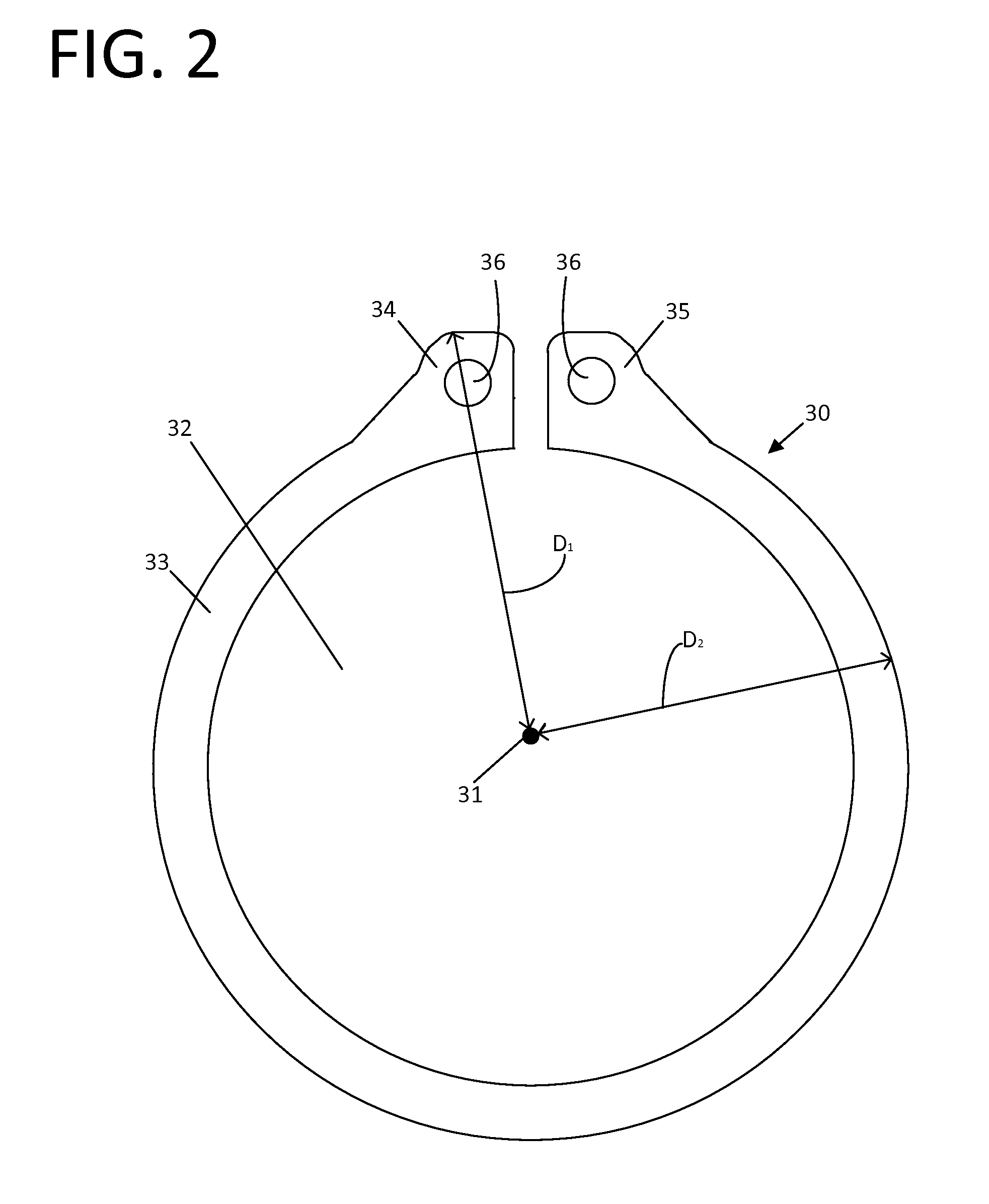
[0017]Turning now to FIGS. 1 and 2, the retaining ring 30 of the present embodiment is shown provided with an axis 31, a central opening 32, defined by a substantially annular portion 33, and first and second lug portions 34, 35. As shown in FIG. 2, the first and second lug portions 34, 35 e...


PUM

PropertyMeasurementUnit
distanceaaaaaaaaaa
centrifugal forceaaaaaaaaaa
forceaaaaaaaaaa

Abstract

The present invention relates to a retained member configured to prevent centrifugal force from disassociating a retaining ring provided with lugs from a groove located on a rotatable shaft when securing the retained member to the rotatable shaft and rotating with the shaft. The retained member includes a substantially annular portion and a retention lip provided with a cutout portion. The substantially annular portion defines an opening sized to receive the rotatable shaft so that the retained member is rotatable with the shaft. The cutout portion is configured to accommodate the lugs when in an installing position as the retained member is snap fit into the groove.

Description

FIELD OF THE INVENTION[0001]The present invention relates to a retaining ring retention system and method and in particular to a retaining ring retention system and method for applications involving centrifugal force.BACKGROUND OF THE INVENTION[0002]Retaining rings are typically used to secure one or more components on a shaft. In a typical application at least one component is slid onto the shaft and then the ring is expanded and snap fit within a groove formed in the end of the shaft. The component(s) cannot be removed without first removing the retaining ring, usually via the use of a retaining ring tool, such as retaining ring pliers, to grasp the lugs and apply a force to spread them apart.[0003]In situations where retaining rings are located on a spinning shaft and subjected to centrifugal force, sufficient centrifugal force can cause the retaining ring to expand radially and dislocate from the retaining groove. Although manufacturers of retaining rings typically publish maxim...

Claims


Application Information

Patent Timeline
Patent Type & Authority Applications(United States)
IPC IPC(8): F16B43/00B23P19/08
CPCB23P19/084F16B43/00F16B1/02F16B21/186
Inventor KAHL, MICHAEL E.
Owner VOLVO LASTVAGNAR AB
Why Eureka
Try Eureka