Bi function LED head lamp using thin shield

Active Publication Date: 2015-10-29
HYUNDAI MOBIS CO LTD
View PDF4 Cites 3 Cited by
  • Summary
  • Abstract
  • Description
  • Claims
  • Application Information

AI Technical Summary

Benefits of technology

[0016]A signal reflection surface is manufactured integrally with a lens holder to reduce th

Problems solved by technology

In general, in a head lamp for a vehicle, an actuator of a bi-function module has a disadvantage in generation of noise, increase of cost, and increase of a weight.
Further, when an LED bi-function is applied, the head lamp for t

Method used


Image

  • Bi function LED head lamp using thin shield
  • Bi function LED head lamp using thin shield

Examples


Embodiment Construction

[0023]Hereinafter, embodiments of the present invention will be described in detail with reference to the accompanying drawings.

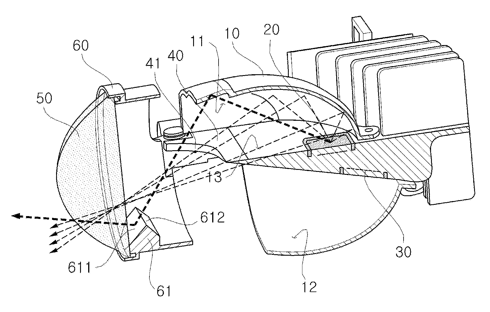
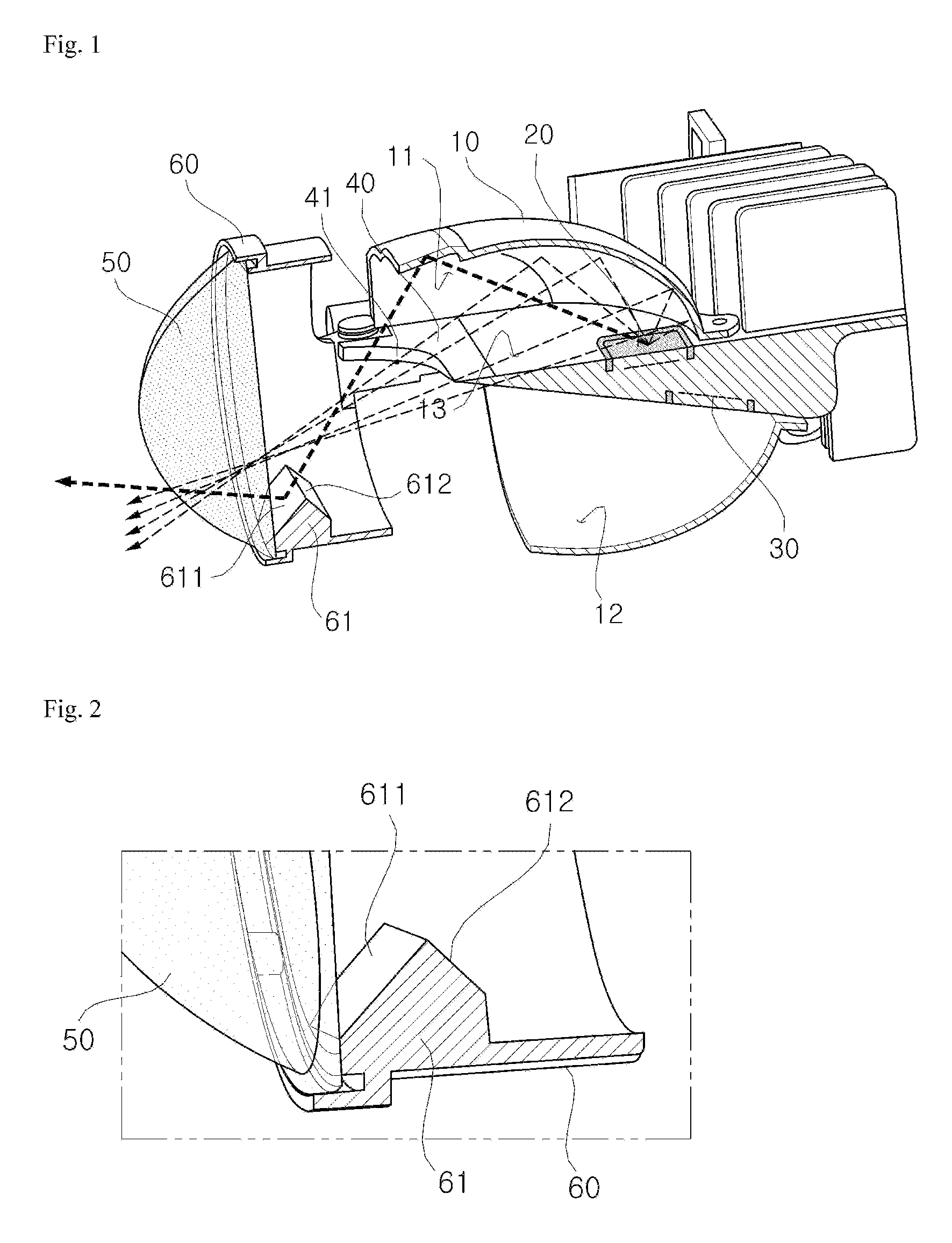
[0024]FIG. 1 is a perspective view of a bi function LED head lamp using a thin shield according to an embodiment of the present invention, and FIG. 2 is an enlarged diagram of a signal reflection surface according to an embodiment of the present invention. Hereinafter, a configuration of a bi function LED head lamp using a thin shield according to embodiments of the present invention will be described with reference to the accompanying drawings.

[0025]The bi function LED head lamp using the thin shield according to embodiments of the present invention includes a reflector 10 reflecting light irradiated from a light source, a low beam light source 20 and a high beam light source 30 installed at upper and lower sides in the reflector 10, and a lens holder 60 of which a rear side is joined to a front surface of the reflector 10, as illustrated in FIG. 1.

[0026]I...


PUM


Abstract

Disclosed is a bi function LED head lamp using a thin shield. The lamp includes: a low beam light source and a high beam light source installed at inner upper and lower sides of a reflector; a shield installed at a front end of the partition in the reflector; a lens holder in which the rear is joined to a front surface of the reflector; and a signal reflection surface installed at an inner lower end of the lens holder. The low beam and the high beam are implemented only by turning on and off an LED through applying the thin shield without an actuator.

Description

CROSS-REFERENCE TO RELATED APPLICATIONS[0001]This application claims priority to and the benefit of Korean Patent Application No. 10-2014-0050039 filed in the Korean Intellectual Property Office on Apr. 25, 2014, the entire contents of which are incorporated herein by reference.TECHNICAL FIELD[0002]The present disclosure relates to a bi function LED head lamp.BACKGROUND ART[0003]In general, in a head lamp for a vehicle, an actuator of a bi-function module has a disadvantage in generation of noise, increase of cost, and increase of a weight. Further, when an LED bi-function is applied, the head lamp for the vehicle can be actuated without the actuator, but a signal reflection surface is impossible to be positioned by applying a shield fixed to the existing position, and as a result, it is difficult to satisfy a signal regulation.[0004]As one example of a vehicular head lamp technique, Korean Patent Unexamined Publication No. 10-2014-0039884 discloses “Head Lamp for Vehicle Which Prev...

Claims


Application Information

Patent Timeline
IPC IPC(8): F21S8/10
CPCF21S48/1747F21S48/1159F21S48/145F21S48/1382F21S48/1233F21S41/295F21S41/28F21S41/255F21S41/321F21S41/338F21S41/43F21S41/60F21S41/663F21S41/365F21S41/148F21W2102/18B60Q1/04F21S41/141F21W2102/13F21W2107/10
Inventor LEE, HYUN SOO
Owner HYUNDAI MOBIS CO LTD
Why Eureka
Try Eureka