Illumination apparatus

a technology of illumination apparatus and illumination, applied in the direction of illuminated signs, display means, instruments, etc., can solve the problems of reducing yield and increasing production costs, and achieve the effect of reducing brightness unevenness and less noticeable non-light emitting regions

Inactive Publication Date: 2015-10-29
KONICA MINOLTA INC
View PDF9 Cites 4 Cited by
  • Summary
  • Abstract
  • Description
  • Claims
  • Application Information

AI Technical Summary

Benefits of technology

[0012]The present invention can thus provide an illumination apparatus that can reduce unevenness in brightness and have a less noticeable non-light emitting region.

Problems solved by technology

Configuring a light emitting source of an organic EL device or the like increased in area, however, entails a larger apparatus required to produce the device and thus results in increased production cost and reduced yield.

Method used


Image

  • Illumination apparatus
  • Illumination apparatus
  • Illumination apparatus

Examples


Embodiment Construction

[0025]Hereinafter reference will be made to the drawings to describe the present invention in embodiments. In describing the embodiments when a number, an amount and the like are referred to, the present invention is not necessarily limited thereto in scope unless otherwise specified. In describing the embodiments, identical or corresponding components are identically denoted and may not be described repeatedly.

[0026]Illumination Apparatus 100

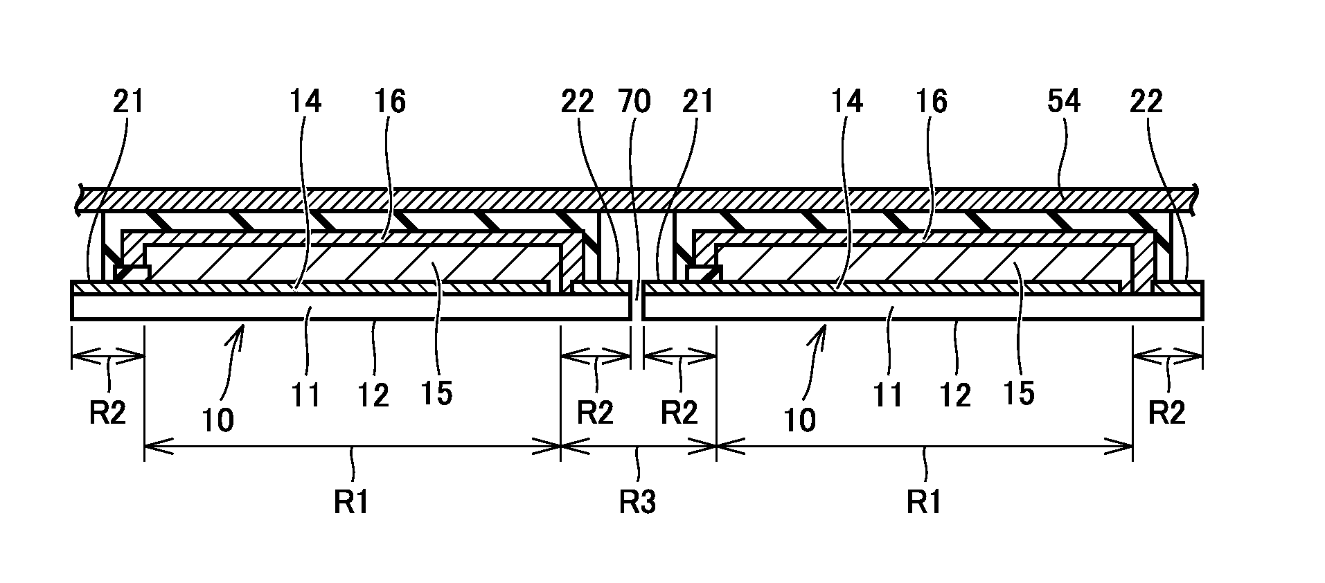
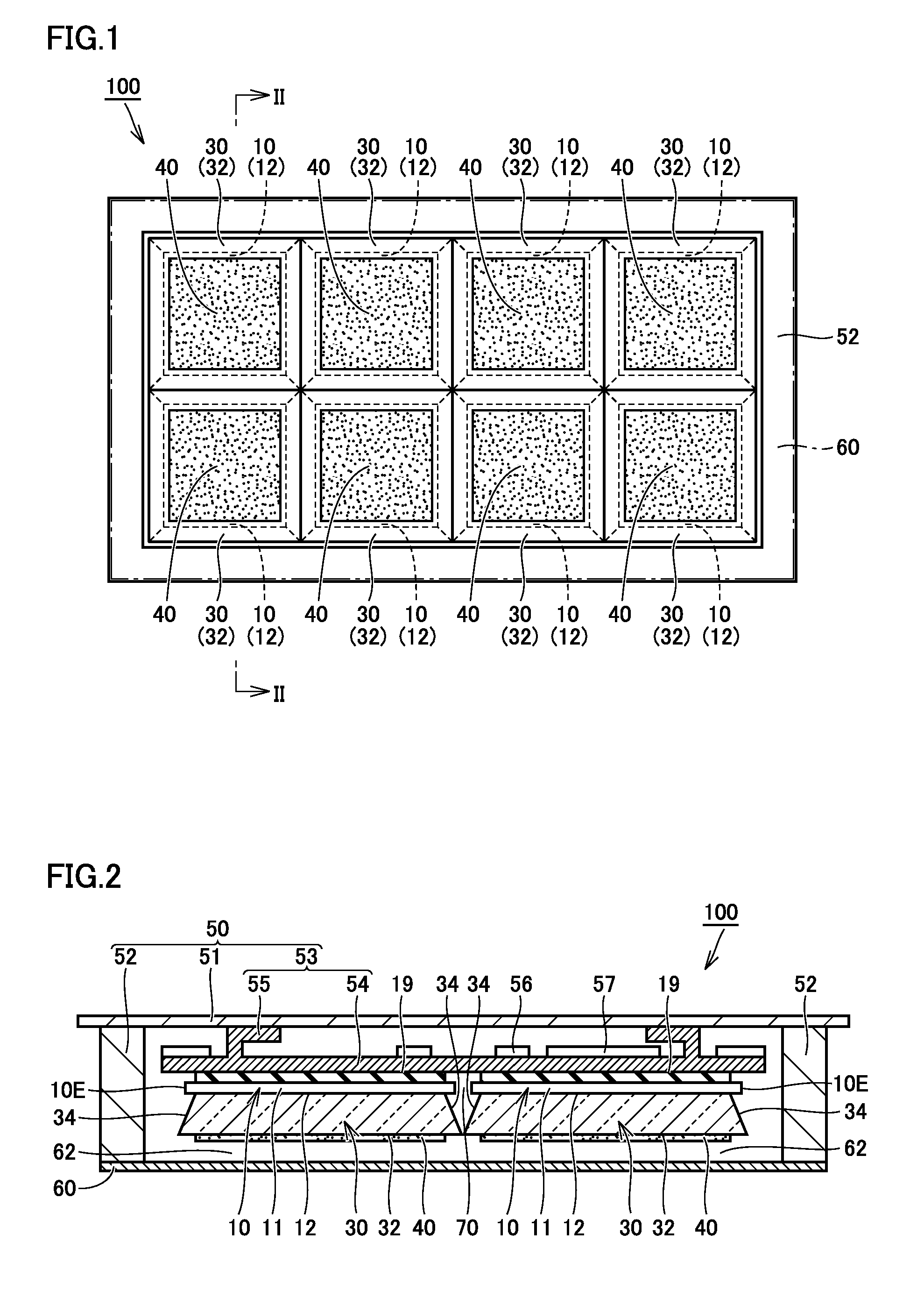
[0027]FIG. 1 is a bottom view of an illumination apparatus 100 of an embodiment. FIG. 1 shows illumination apparatus 100 as seen at a front surface 12 (or a light emitting surface) of a light emitting panel 10 used for illumination apparatus 100. FIG. 2 is a cross section that is taken along an arrowed line II-II shown in FIG. 1 and is seen in a direction indicated by arrows.

[0028]For the sake of illustration, FIG. 1 shows illumination apparatus 100 with a light diffusion plate 60 (see FIG. 1 and FIG. 2) represented transparently by long dashed...


PUM


Abstract

An illumination apparatus includes: a plurality of light emitting panels each having a surface with a light emitting region and a non-light emitting region; a light guiding member having a light incidence face and a light exit face, with the light incidence face opposite to the surface of the light emitting panel; a reflector opposite to the non-light emitting region, and reflecting the light incident on the light guiding member; a light attenuator on the light exit face opposite to the light emitting region, and attenuating the light outputted through an area on the light exit face, the area being opposite to the light emitting region; and a light diffusion member opposite to the light guiding member with a gap therebetween.

Description

TECHNICAL FIELD[0001]The present invention relates to an illumination apparatus and more specifically to an illumination apparatus including a plurality of light emitting panels disposed in a plane.BACKGROUND ART[0002]In recent years, an illumination apparatus including an organic EL (OLED: organic electroluminescence) or similar light emitting panel as a light emitting source, is attracting attention. As there is an increasing demand for large sized illumination apparatuses, there is also a need for light emitting sources having larger areas. A light emitting source may be increased in area by enlarging the area of a light emitting panel that configures the light emitting source. Configuring a light emitting source of an organic EL device or the like increased in area, however, entails a larger apparatus required to produce the device and thus results in increased production cost and reduced yield.[0003]To prevent increased production cost and reduced yield, there is a method known...

Claims


Application Information

Patent Timeline
Patent Type & Authority Applications(United States)
IPC IPC(8): F21V8/00
CPCG02B6/0088G02B6/0031G02B6/0078G02B6/005G02B6/0051H10K50/856
Inventor SANDO, YASUHIROHIRAO, YUSUKENAITO, MITSUYOSHIWAKAHARA, JUNYA
Owner KONICA MINOLTA INC
Why Eureka
Try Eureka