Method of misalignment correction and diagnostic function for lane sensing sensor

a technology of lane sensing sensor and diagnostic function, which is applied in the field of lane sensing calibration of vision sensors, can solve problems such as hindering the vehicle and skewed lane sensing systems

Active Publication Date: 2015-10-29
GM GLOBAL TECH OPERATIONS LLC
View PDF1 Cites 4 Cited by
  • Summary
  • Abstract
  • Description
  • Claims
  • Application Information

AI Technical Summary

Benefits of technology

[0004]An advantage of an embodiment is an autonomous detection of a misalignment of the image capture device in a lane sensing system and autonomous correction of an angle misalignment. The system utilizes parameters with respect to the vehicle and the road, such as the vehicle yaw rate, vehicle lateral offset, vehicle heading, vehicle speed, lane curvature, and an estimate

Problems solved by technology

Vision sensors require proper alignment; otherwise, results from the lane sensing system may be skewed.
Any angle misalignment in the vision image device would result inaccurate posi

Method used


Image

  • Method of misalignment correction and diagnostic function for lane sensing sensor
  • Method of misalignment correction and diagnostic function for lane sensing sensor
  • Method of misalignment correction and diagnostic function for lane sensing sensor

Examples


Embodiment Construction

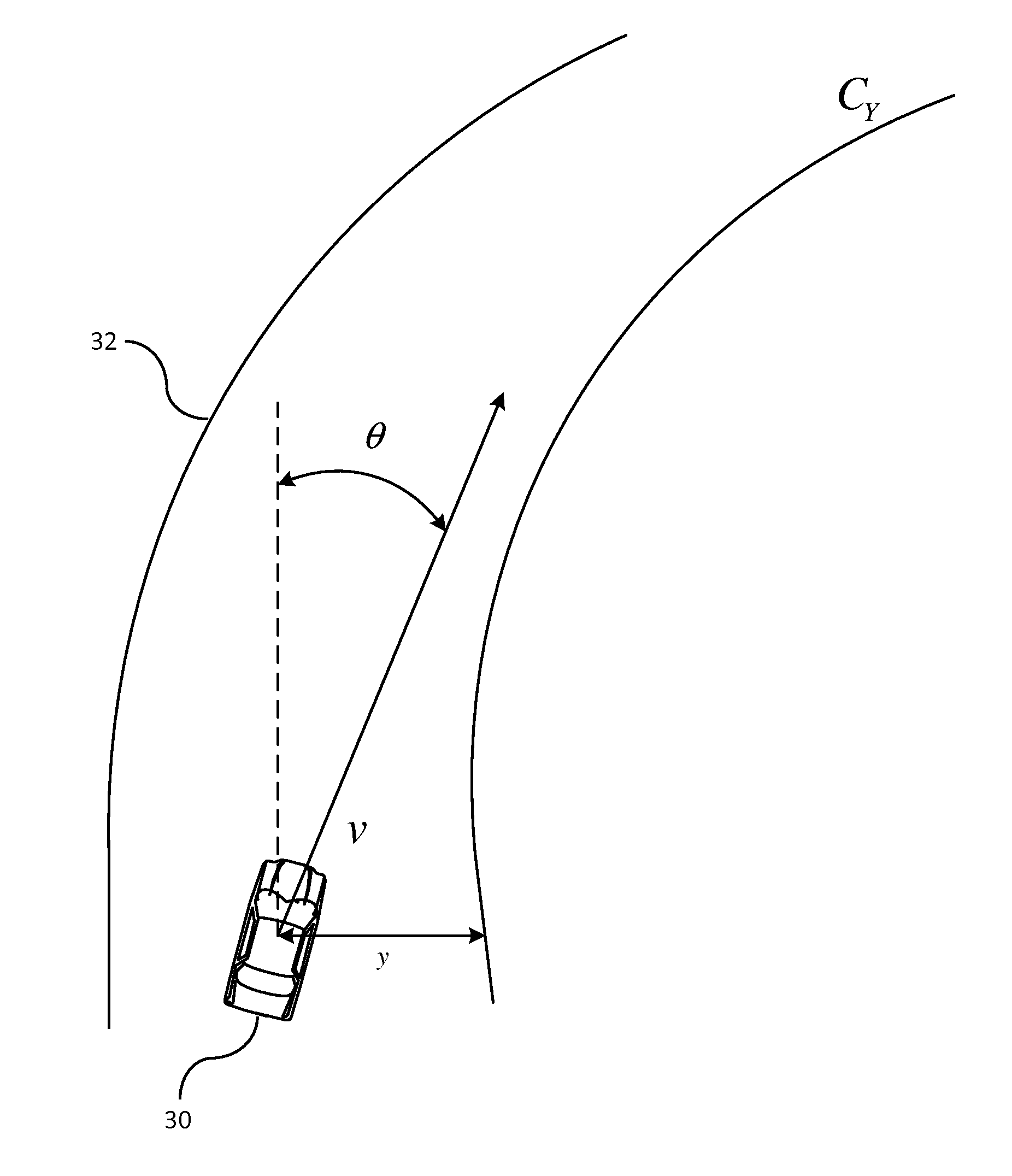
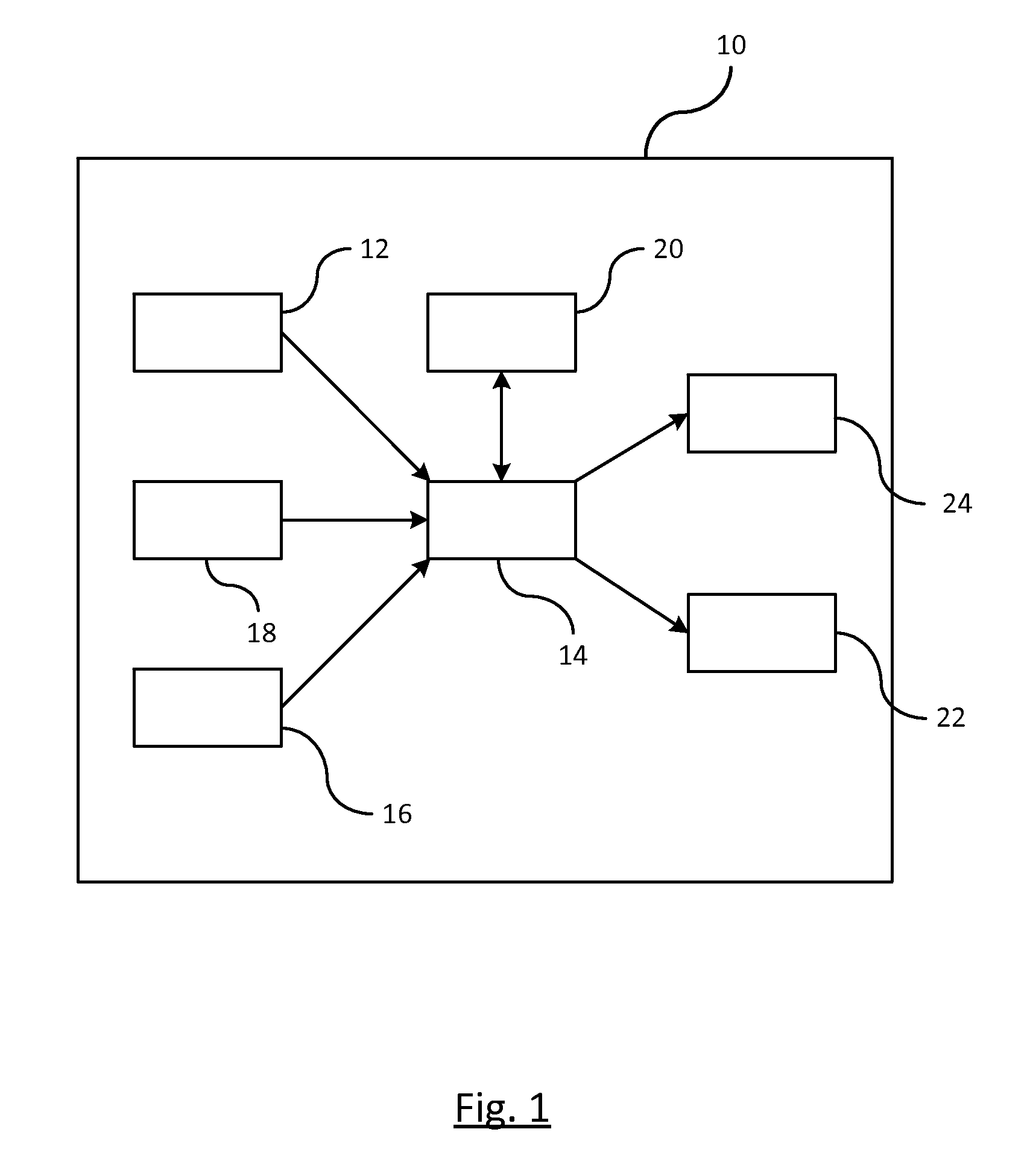
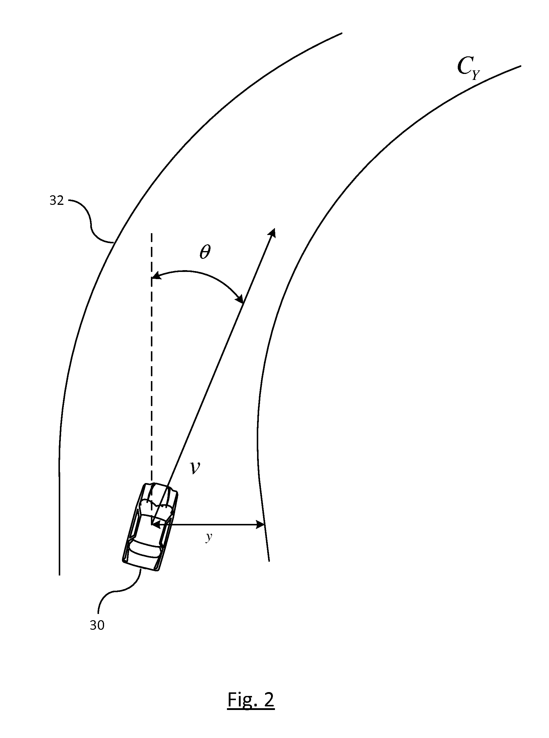
[0013]There is shown in FIG. 1 a vision angle misalignment system 10 for detecting a state of health of a vision-based lane sensing system. The vehicle system 10 analyzes a vision system used by the vehicle such as but not limited to, lane departure warning systems or lane centering systems, for determining whether any misalignment has occurred with respect to the vision system. The vehicle system 10 includes a vision-based capture device 12 for capturing images exterior of the vehicle. A processor 14 receives data obtained by the vision-based capture device 12 and analyzes the data for determining any substantial violations in the lane sensing system. The vision-based capture device 12 may be used to detect a vehicle heading θ, vehicle lateral offset y, an estimated curvature of an expected path of travel of the vehicle CY, a lane curvature of a traveled road CL.

[0014]A yaw rate sensor 16 or similar device may be used to determine a yaw rate of the vehicle. A vehicle speed sensor 1...


PUM


Abstract

A method of diagnosing a state of health of a vision-based lane sensing system. A first misalignment factor is calculated as a function of a vehicle lateral offset and a vehicle heading. A second misalignment factor is calculated as a function of a vehicle speed, an estimated curvature of an expected path of travel, a lane curvature, and the vehicle heading. Histograms are generated for the first and second misalignment factors. A probability of a state of health is determined. A determination is made whether the probability of the state of health is within a predetermined threshold. An angle misalignment of the vision system is estimated. The angle misalignment of the vision system is corrected in response to the determination that the probability of the state of health is within the predetermined threshold; otherwise a warning of a faulty lane sensing system is actuated.

Description

BACKGROUND OF INVENTION[0001]An embodiment relates to lane sensing calibration for vision sensors of a lane sensing system.[0002]A lane departure warning system and lane centering system are a couple examples of vehicle systems designed to either warn a driver when the vehicle begins to unintentionally move out of its lane or maintain a vehicle in its lane. Visions systems are one of the devices typically used for sensing the lane of the road of travel. Vision sensors require proper alignment; otherwise, results from the lane sensing system may be skewed. For example, a forward facing image capture device captures a scene exterior of the vehicle in a forward direction. Typically the forward facing capture device would be aligned with a centerline of the vehicle if mounted on the centerline of the vehicle. Any angle misalignment in the vision image device would result inaccurate positioning of the vehicle in the lane which would ultimately hinder the vehicle from properly detecting d...

Claims


Application Information

Patent Timeline
IPC IPC(8): H04N17/00G06K9/00G06T7/00G06V10/24
CPCH04N17/002G06T7/0018G06T2207/20076G06T2207/30256G06K9/00798G06V20/588G06T7/0002G06T2207/30168G06T7/80G06V10/24
Inventor ZENG, SHUQINGSONG, XIAOFENG F.
Owner GM GLOBAL TECH OPERATIONS LLC
Why Eureka
Try Eureka