
Apparatus And Methods For Purging Catheter Systems

a catheter system and catheter technology, applied in the field of catheter system apparatus and methods, can solve the problems of interruption of therapy, partial or complete blockage, and requiring expensive and potentially dangerous methods

Active Publication Date: 2015-11-05
BECTON DICKINSON & CO
View PDF17 Cites 17 Cited by
  • Summary
  • Abstract
  • Description
  • Claims
  • Application Information

AI Technical Summary

Benefits of technology

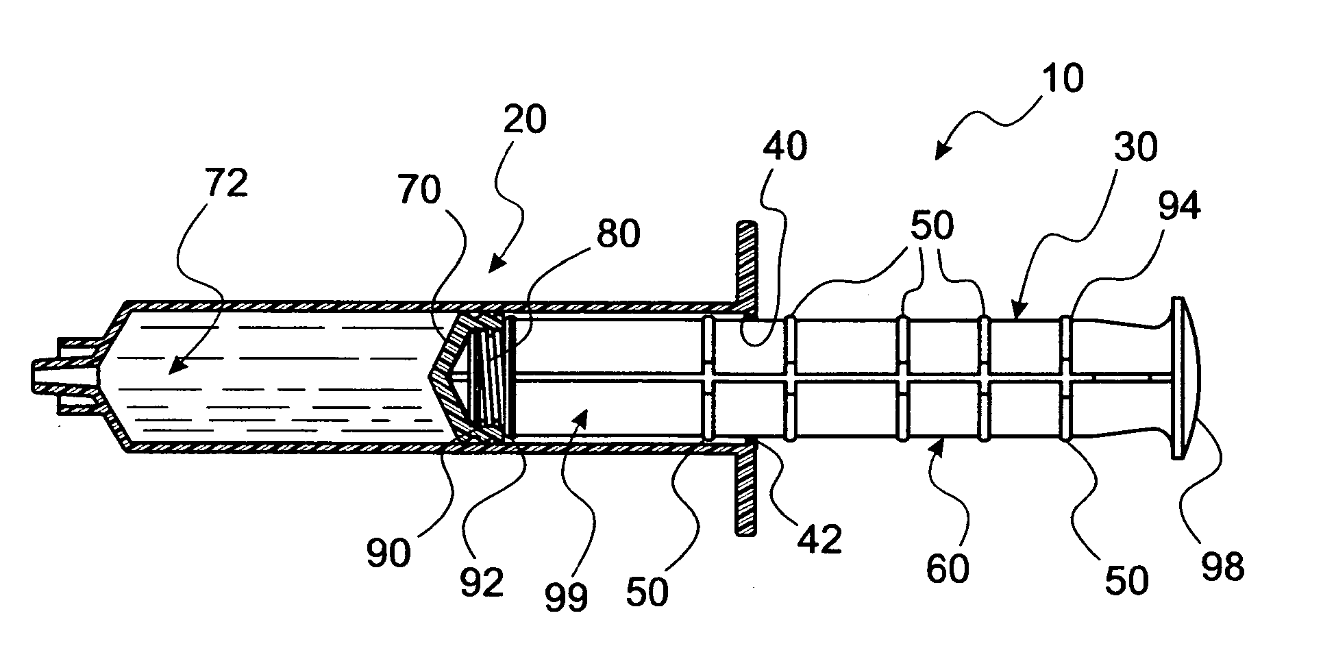
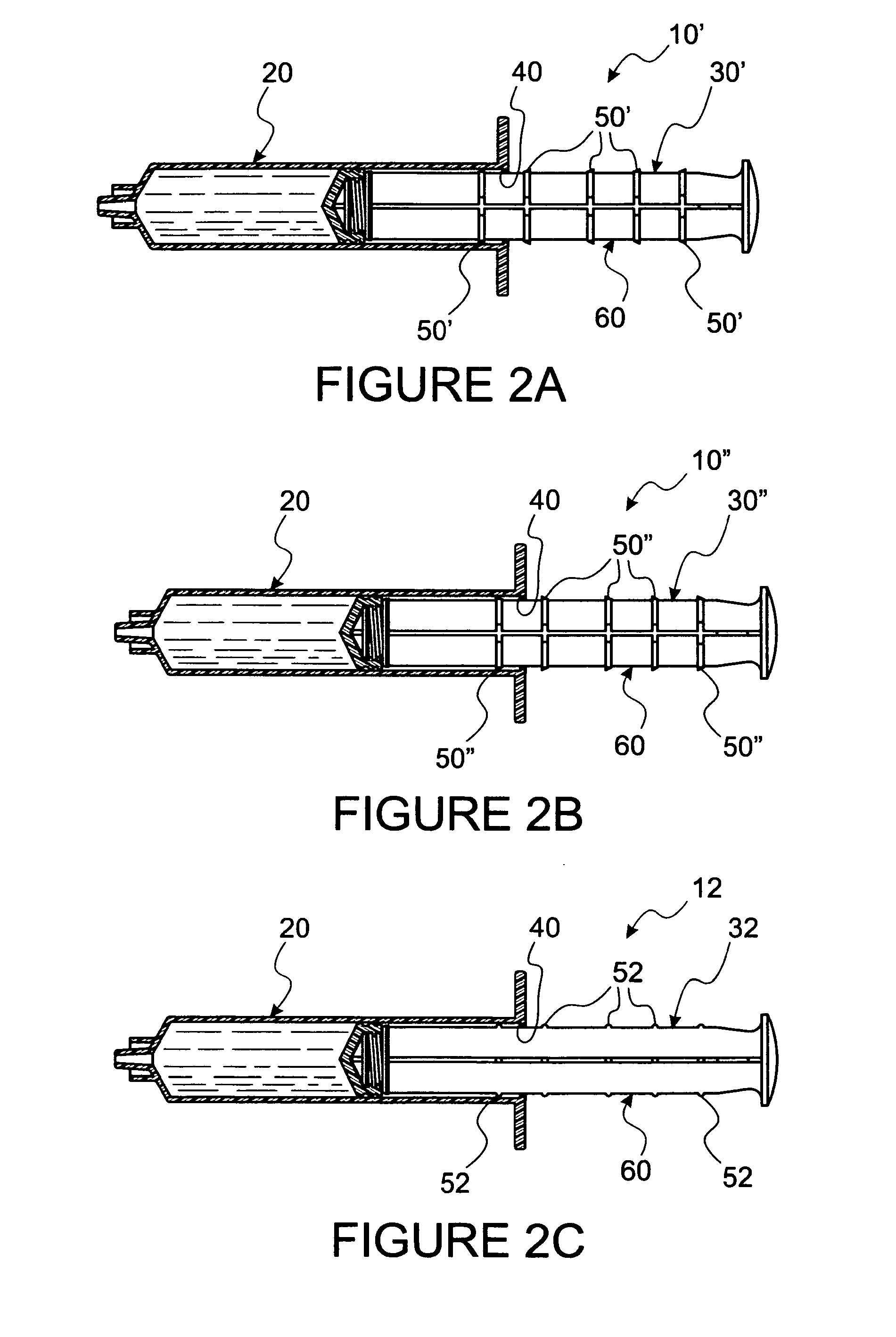
[0022]At least one actuating geometry, sized and shaped to require a predetermined force to displace the actuating geometry past the retention ring, is disposed proximally on the stem relative to the entry disk. Forcing the actuating geometry past the retention ring yields the force necessary to provide desired turbulent flushing fluid pressure and initiate flow. Such geometry may be a disk on the plunger or an interfacing nub on exterior edges of shafts of a plunger rod. Reflexive motion associated with forcing the actuating disk past the retention disk provides the memory based, stored energy necessary to assure continuation of forced flow thereby providing the pressure pulse. The length of the pressure pulse is determined by either the plunger being displaced to empty the syringe barrel or a second actuating disk disposed proximally on the stem relative to the actuating disk just forced through the retention ring to provide a tactilely determinable stop. Note, that resistance of this stop, relative to reflexive energy applied to displace the syringe plunger rod, provides the hysteresis specified. In this manner, a conventional syringe barrel, in combination with a plunger rod made according to specifications of the instant invention, can provide desired pulse-pause pressure pulses from a syringe substantially independent of a syringe user. It may be preferred to provide a segment of a plunger rod free of actuating geometry to provide a “no-pulse” segment to enable conventional flush technique to check for possible occlusions and to verify blood return.
[0029]Accordingly, it is a primary object to provide apparatus which provides substantially user independent, controlled pulse-pause pulsatile flow of sufficiently turbulent flushing pressure and flow within a catheter system to substantially purge the line of unwanted residue.

Problems solved by technology

Such build-up can cause partial or complete blockage of the fluid pathway in a catheter system, requiring expensive and potentially dangerous methods for purging the catheter or necessitating a total catheter exchange.
Often, such blockages lead to interruptions in therapy (e.g. IV therapy) that may compromise patient care.
Further, build-up of residue within a catheter can also increase infection risk by providing a breeding medium for microorganisms.
However, efficiency and success of catheter purging using push-pause flushing is well known to be completely dependent upon individual awareness, compliance and technique and a successful purging operation is often incomplete and problematic.
For this reason, many users may not use such turbulent flushing effectively while others, due to lack of knowledge or perception of value, may not use it at all.
Generally, these stops are hard and cannot be reasonably overcome, as is common in single-use hypodermic syringes.
Even so, there are no teachings in Kleyman for providing momentary stops which produce a predetermined amount of turbulent flow in a catheter.
Just as clinician-dependent generation of push-pause flow is problematic, all such art is void of teachings which assure successful creation of turbulent flow for clearing an associated attached catheter system.

Method used


Image

  • Apparatus And Methods For Purging Catheter Systems
  • Apparatus And Methods For Purging Catheter Systems
  • Apparatus And Methods For Purging Catheter Systems

Examples


Embodiment Construction

[0060]In this description, the term proximal is used to indicate the segment of the device normally closest to the object of the sentence describing its position. The term distal refers to a site opposite the proximal section. Reference is now made to the embodiments illustrated in FIGS. 1-20 wherein like numerals are used to designate like parts throughout.

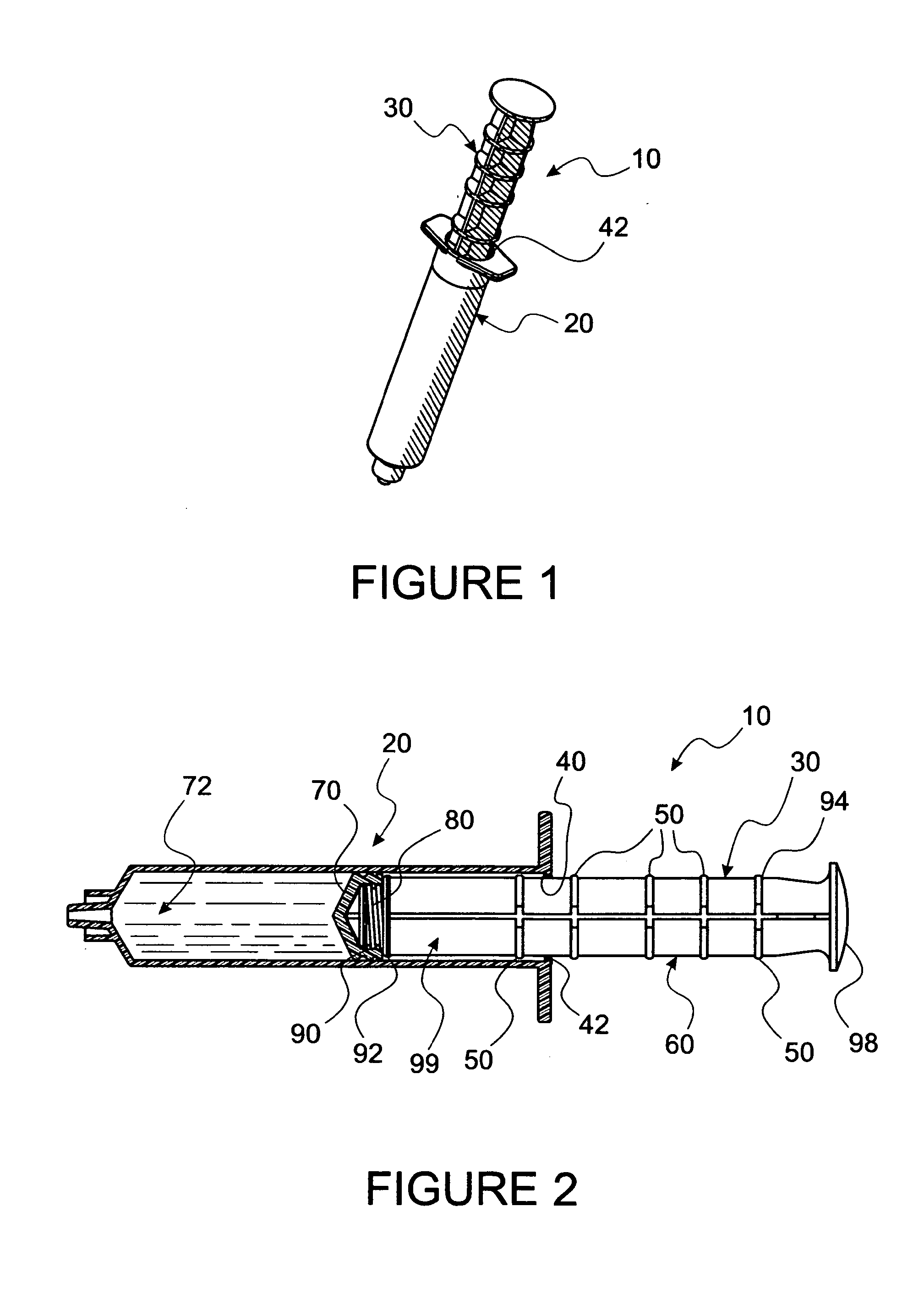
[0061]Reference is now made to FIG. 1 wherein a preferred embodiment of a syringe / plunger rod combination 10 of the instant invention is seen. Combination 10 comprises a conventional syringe barrel 20 and a plunger rod 30. Salient features of combination 10 are better seen in FIG. 2 to comprise barrel 20 having a retention ring 40 disposed at proximal barrel hole opening 42 and plunger rod 30 comprising a plurality of actuating geometry, interfaces or rings, generally numbered 50) disposed along a stem 60 thereof. In addition, as is common with plunger rods of conventional syringes, plunger rod 30 has a plunger 70 affixed to the ...


PUM


Abstract

Apparatus and methods for providing controlled pressure-flow pulses which purge a catheter system with turbulent flow flushing. Accomplishment of such controlled pressure-flow pulses is provided by a variety of inventive devices including a special plunger rod for a conventional syringe, other interactive parts for conventional syringes, an in-line catheter attachable device which automatically generates the controlled pressure-flow pulses and also single pulse, digitally operated devices.

Description

CONTINUITY[0001]This non-provisional U.S. patent application is a continuation-in-part of a provisional U.S. Patent Application No. 61 / 192,827 filed Sep. 23, 2008, titled TURBULENT FLOW SYRINGE AND FLUID PATHWAY INSERT.FIELD OF INVENTION[0002]This invention is associated with apparatus and methods for clearing catheter systems (e.g. IV lines) by creating controlled and consistent turbulent flushing pressure and flow within the system to purge the line of unwanted residue, and, in particular, the invention is associated with apparatus and methods for creating such turbulent flushing pressure and flow substantially independent of clinician technique.BACKGROUND AND RELATED ART[0003]It is well known in IV care art that turbulent “start-stop” or “push-pause” flushing of IV catheters, e.g. central venous catheters, has become an accepted method for purging matter from catheters and, thereby, preventing build-up of deposits of blood, blood residue and IV drugs within a catheter. Such build...

Claims


Application Information

Patent Timeline
Patent Type & Authority Applications(United States)
IPC IPC(8): A61M5/315A61M25/00
CPCA61M5/31505A61M25/00A61M2005/31508A61M2005/3128A61M2025/0019A61M5/1424A61M5/31501A61M5/31511A61M5/31595A61M5/502A61M39/24A61M2005/1403A61M2039/242A61M2205/071A61M2206/10A61M39/22A61M39/225
Inventor HOWLETT, MICHAEL W.MERCER, JAMES V.PAOLUCCI, AMELIO
Owner BECTON DICKINSON & CO
Learn More