LED Light Fixture

a technology of led light fixtures and led modules, applied in the field of light fixtures, can solve the problems of heat dissipation, high temperature of high-luminance led light fixtures, and the particular challenges of high-luminance led light fixtures, and achieve the effect of improving fin efficiency

Active Publication Date: 2015-11-05
IDEAL IND LIGHTING LLC
View PDF1 Cites 10 Cited by
  • Summary
  • Abstract
  • Description
  • Claims
  • Application Information

AI Technical Summary

Benefits of technology

[0017]In some of such embodiments, the fins extend farther from the base in the central region than in the peripheral regions. Because the airflow velocity is higher in the center than along the periphery, fins being taller in the center enhances the fin efficiency for the given airflow.
[0021]The flow deflectors facilitate effectiveness of the heat-dissipating region and the overall efficiency of heat removal from the entire heat sink for substantially uniform temperatures thereacross.
[0029]Some versions of the inventive LED light fixture may also include an inner deflector along the at least one inner venting aperture. The inner deflector has a pair of oppositely-facing beveled deflector surfaces each angled off-vertical in substantially common direction as the beveled rear surface of the adjacent lens member and oriented to further accelerate and redirect inwardly upward air flow from the peripheral venting aperture toward the heat-dissipating surfaces.

Problems solved by technology

High-luminance light fixtures using LED modules as light source present particularly challenging problems.
One particularly challenging problem for high-luminance LED light fixtures relates to heat dissipation.
Another challenge is that LEDs that produce high temperatures during operation and that other fixture portions need to be isolated or insulated for such high temperatures in order to maintain lower operating temperatures permitted for other parts of the fixture.

Method used


Image

  • LED Light Fixture
  • LED Light Fixture
  • LED Light Fixture

Examples


Embodiment Construction

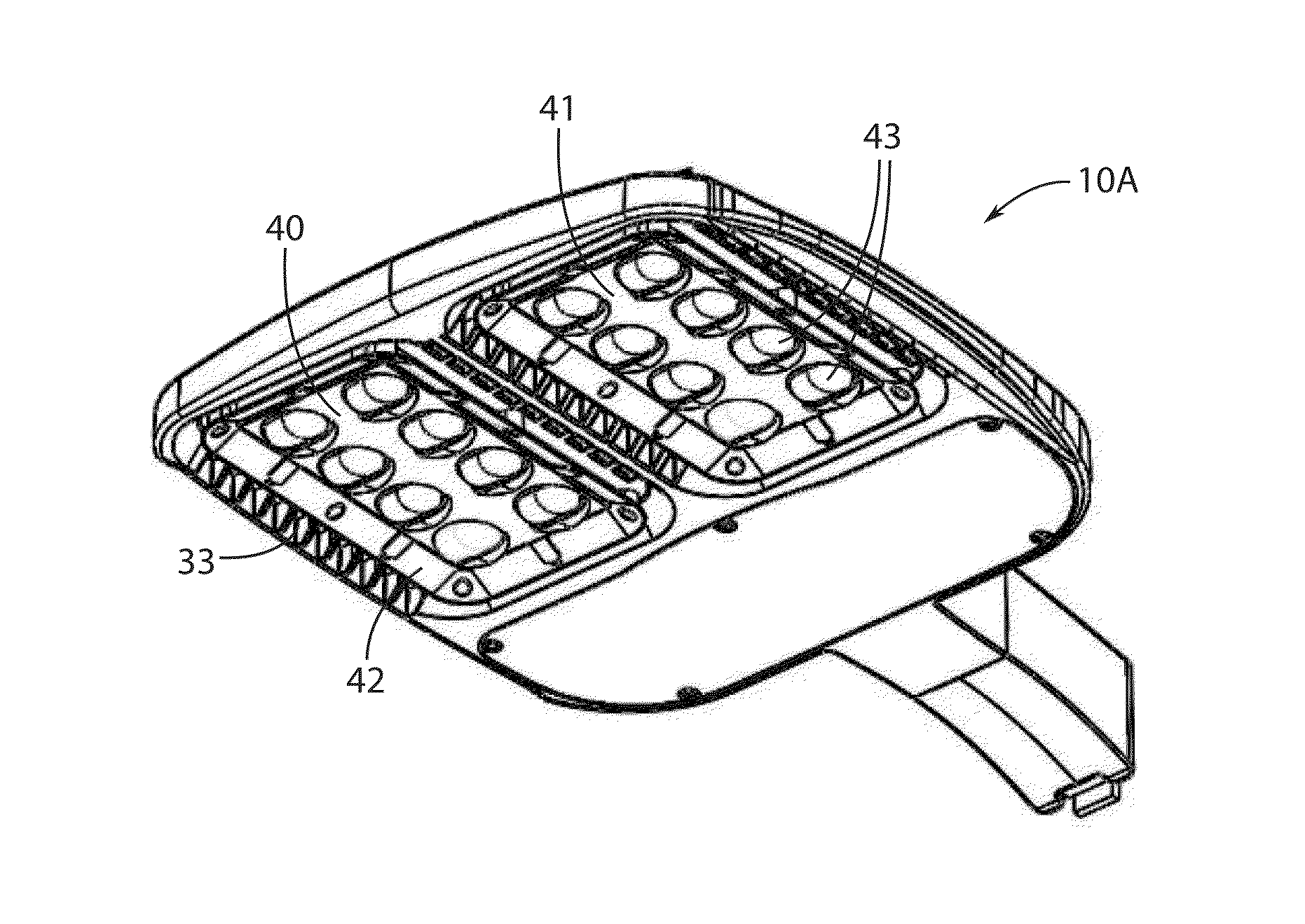
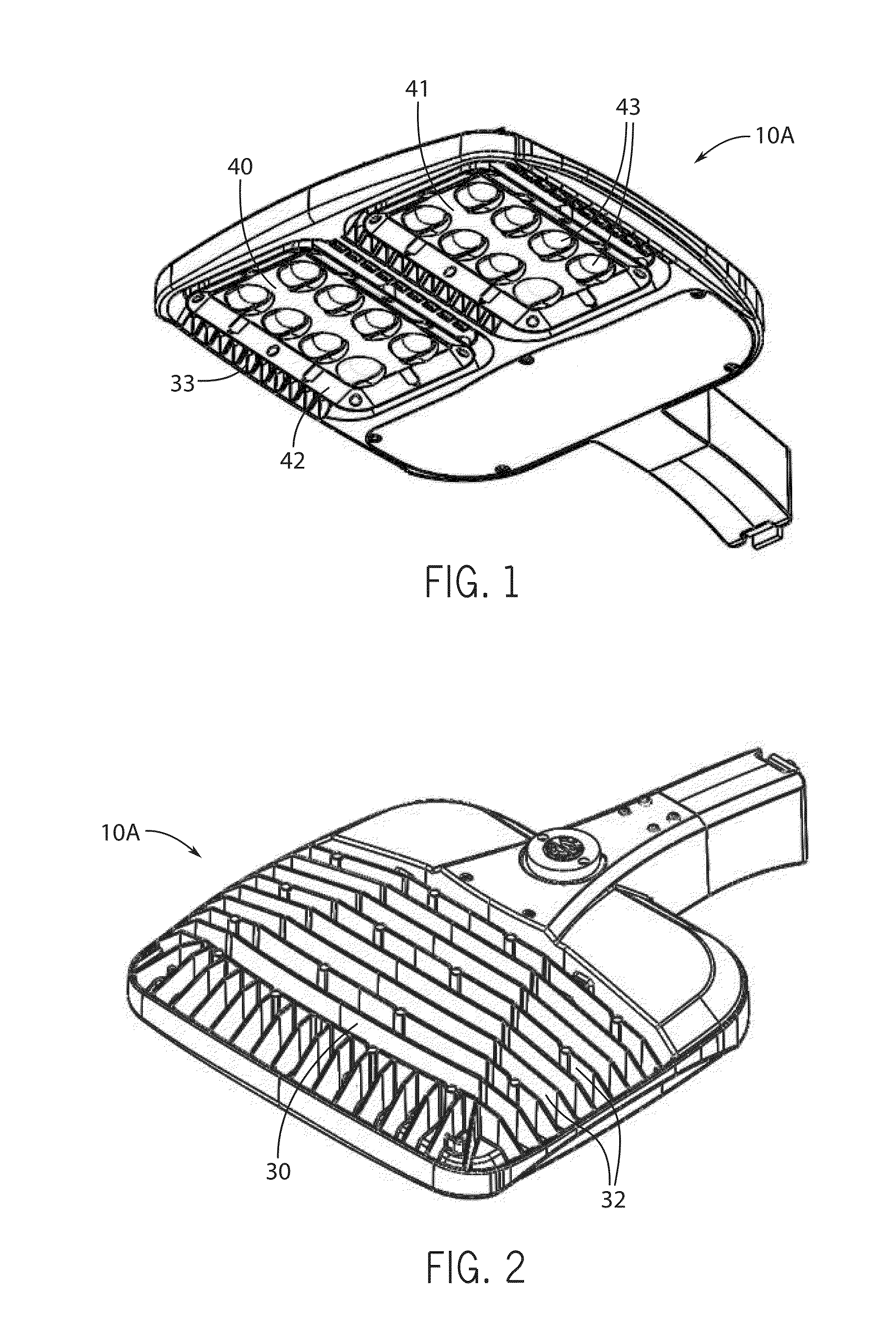
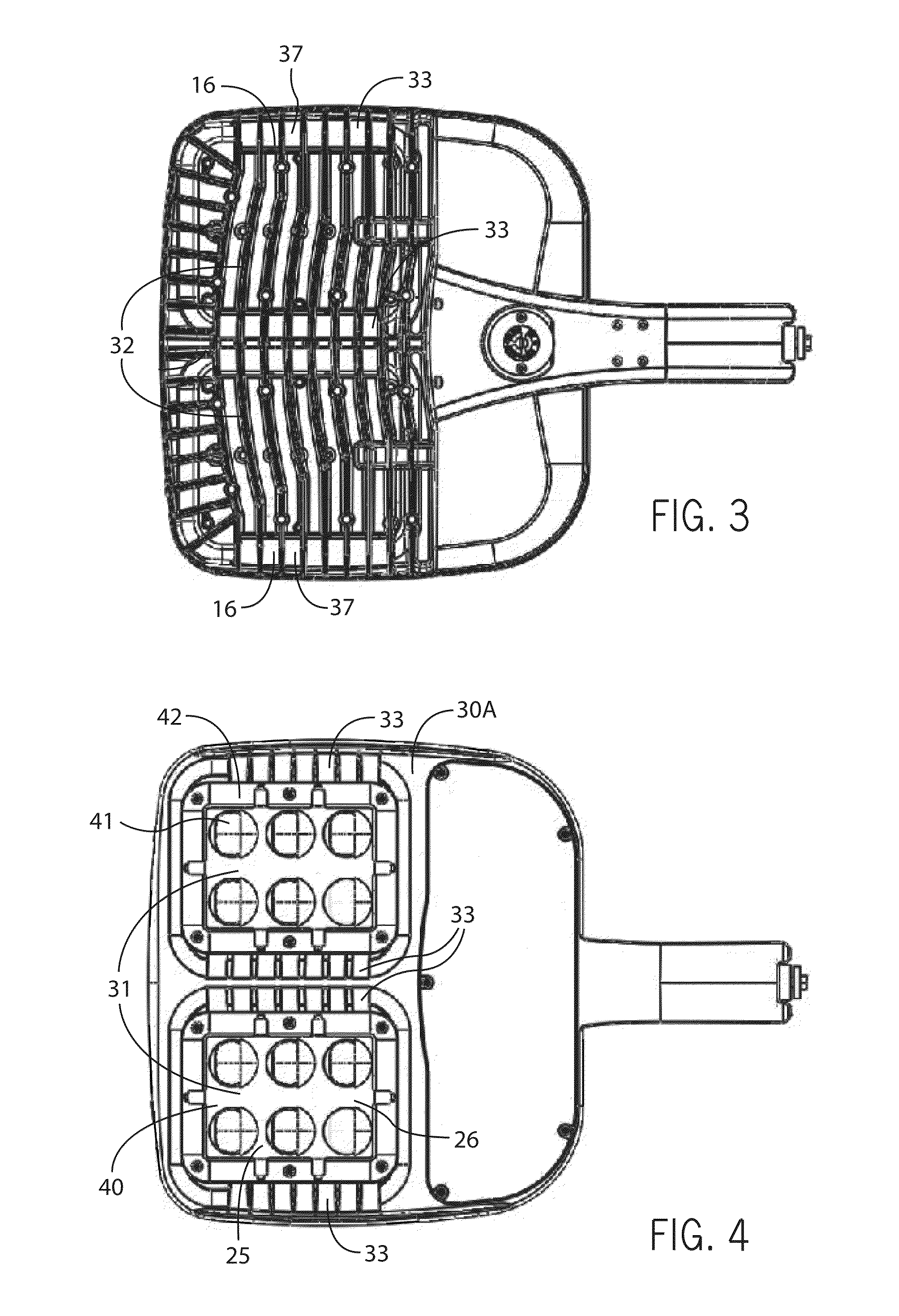
[0082]The figures illustrate exemplary embodiments of LED light fixtures in accordance with this invention. Common or similar parts in different embodiments are given the same numbers in the drawings; the light fixtures themselves are often referred to by the numeral 10 followed by different letters with respect to alternative embodiments.

[0083]FIGS. 1-17 and 27-38 illustrate a light fixture 10 which includes at least one LED light source 20 and a heat-conductive structure 30 (also referred hereto as a heat sink) including an LED-supporting region 31 and heat-dissipating surfaces 32 extending away therefrom. FIGS. 1, 4, 5 and 27-34 illustrate one embodiment of light fixture 10A which includes a pair of LED light sources 20A each including a plurality of LED emitters 21. FIG. 35 shows another embodiments of light fixture 10B which has a single LED light source 20B with a plurality LED emitters 21. LED light sources 20 are thermally coupled to LED-supporting region 31. As seen in FIGS...


PUM


Abstract

An LED light fixture including at least one LED light source thermally coupled to a heat-conductive structure. The heat-conductive structure having an LED-supporting region and heat-dissipating surfaces extending away therefrom. The at least one LED light source is thermally coupled to the LED-supporting region. The heat-conductive structure defines venting apertures bordering the at least one LED light source to facilitate ambient fluid flow to and from the heat-dissipating surfaces. In some embodiments, the LED light fixture includes a protrusion extending into a corresponding one of the venting apertures and oriented to direct air flow. In certain embodiments, the heat-conductive structure defines a plurality of venting apertures adjacent the at least one LED light source, the heat-dissipating surfaces include fins increasing in height at positions adjacent to the at least one of the venting apertures.

Description

FIELD OF THE INVENTION[0001]This invention relates to light fixtures and, more particularly, to light fixtures using light-emitting diodes (LEDs).BACKGROUND OF THE INVENTION[0002]In recent years, the use of light-emitting diodes (LEDs) in development of light fixtures for various common lighting purposes has increased, and this trend has accelerated as advances have been made in the field. Indeed, lighting applications which previously had typically been served by fixtures using what are known as high-intensity discharge (HID) lamps are now being served by LED light fixtures. Such lighting applications include, among a good many others, roadway lighting, factory lighting, parking lot lighting, and commercial building lighting.[0003]High-luminance light fixtures using LED modules as light source present particularly challenging problems. One particularly challenging problem for high-luminance LED light fixtures relates to heat dissipation. Among the advances in the field are the inve...

Claims


Application Information

Patent Timeline
Patent Type & Authority Applications(United States)
IPC IPC(8): F21V29/83F21V29/70F21V5/04F21V29/74F21K99/00F21V29/503F21V23/02
CPCF21V29/83F21V29/503F21V29/70F21Y2101/02F21V29/74F21K9/50F21V5/04F21V23/023F21W2131/10F21Y2115/10F21K9/60F21Y2101/00
Inventor KINNUNE, BRIANPAWAR, SANDEEPMEDENDORP, JR., NICHOLAS W.GOELZ, DAVID P.SNELL, NATHAN
Owner IDEAL IND LIGHTING LLC
Why Eureka
Try Eureka